User’s Manual of MG-11x Modbus Gateway Series RS232/RS422/RS485 Modbus Gateway Series MG-110 / MG-115AT / MG-120 1
User’s Manual of MG-11x Modbus Gateway Series Trademarks Copyright © PLANET Technology Corp. 2020. Contents are subject to revision without prior notice. PLANET is a registered trademark of PLANET Technology Corp. All other trademarks belong to their respective owners.
User’s Manual of MG-11x Modbus Gateway Series TABLE OF CONTENTS 1. INTRODUCTION .................................................................................................................... 5 1.1 Packet Contents ............................................................................................................................................. 5 1.2 Product Description ............................................................................................................................
User’s Manual of MG-11x Modbus Gateway Series 4.2.1 System ................................................................................................................................................................. 38 4.2.2 Port ...................................................................................................................................................................... 40 4.2.3 Device ..............................................................................................
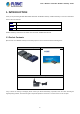
User’s Manual of MG-11x Modbus Gateway Series 1. INTRODUCTION Thank you for purchasing PLANET MG-110/MG-115A/ MG-120 Modbus Gateway. “Modbus Gateway” is used as an alternative name in this User’s Manual. MG-110 1-Port RS232/422/485 Modbus Gateway MG-115A 1-Port RS232/422/485 Modbus Gateway with 1-Port 100BASE-FX SFP MG-120 2-Port RS232/422/485 Modbus Gateway “Modbus Gateway” mentioned in this Guide refers to the MG-110/MG-115A/ MG-120. 1.
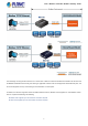
User’s Manual of MG-11x Modbus Gateway Series 1.2 Product Description Standard Modbus TCP/RTU/ASCII Network Integration PLANET MG-11x 1-port RS232/422/485 Modbus Gateway Series supports the standard Modbus Protocol, which makes it possible for converting any Modbus Protocols between Modbus TCP, Modbus RTU, and Modbus ASCII for all supported hardware interfaces. Its serial protocol can be used for industrial automation where SCADA or HMI system is in place.
User’s Manual of MG-11x Modbus Gateway Series The advantage of having the MG-11x Series is to assist users to build an environment between the Modbus TCP Protocol and the Modbus RTU/ASCII Protocol easily, thus offering an application solution to the control equipment without Ethernet ports, and the control equipment can only control through a PC workstation or control panel.
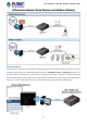
User’s Manual of MG-11x Modbus Gateway Series Remote Management The MG-11x Series makes the connected Modbus RTU/ASCII equipment become IP-based facilities and is able to connect to the Modbus TCP/IP network via its R232/422/485 serial interface and 10/100BASE-TX RJ45 or 100BASE-FX Ethernet port. It provides a remote web management and telnet interface for efficient remote network management.
User’s Manual of MG-11x Modbus Gateway Series Modbus Serial Port State Monitoring The MG-11x Series shows the details of the total bytes transmitted and received on the RS232/422/485 serial interface, and the detailed total number of frames transmitted and received on the remote web/telnet management interface. This function allows network administrator to check the status and statistics of the MG-11x Series via the single RS232/422/485 serial interface.
User’s Manual of MG-11x Modbus Gateway Series 1.3 How to Use This Manual This User’s Manual is structured as follows: Section 2, INSTALLATION It explains the functions of the MG-11x Series and how to physically install the MG-11x Series. Section 3, MODBUS GATEWAY MANAGEMENT The chapter explains how to manage the MG-11x Series in different ways. Section 4, WEB CONFIGURATION It describes how to configure by web interface.
User’s Manual of MG-11x Modbus Gateway Series 1.
User’s Manual of MG-11x Modbus Gateway Series 1.5 Product Specifications Product MG-110 MG-115A MG-120 Serial Interface Serial Port 1 x DB9 male Serial Standards RS232/RS422/4-wire RS485/2-wire RS485 Baud Rate (Data Rate) 50bps to 921Kbps Data Bits 5, 6, 7, 8 Stop Bit 1, 1.
User’s Manual of MG-11x Modbus Gateway Series Mechanical Reset Button Metal < 5 sec: System reboot > 5 sec: Factory default Management Web management Telnet Console management Management Interfaces Windows-based VCOM Utility management SNMPv1, v2c / SNMP Trap UNI-NMS monitoring PLANET Smart Discovery Utility IP Version IPv4 RTU Master Operation Mode RTU Slave ASCII Master ASCII Slave Windows-based Only: Windows XP Windows Server 2003 Virtual COM Utility Windows 7 Platform Supports Windows Server
User’s Manual of MG-11x Modbus Gateway Series Note.
User’s Manual of MG-11x Modbus Gateway Series 2. INSTALLATION This section describes the hardware features and installation of the Modbus Gateway' components on the desktop or rack. For easier management and control of the Modbus Gateway, familiarize yourself with its display indicators, and ports. Front panel illustrations in this chapter display the LED indicators. Before connecting any network device to the Modbus Gateway, please read this chapter completely. 2.1 Hardware Description 2.1.
User’s Manual of MG-11x Modbus Gateway Series 16
User’s Manual of MG-11x Modbus Gateway Series MG-115A: 94 x 70 x 26mm (W x D x H) 17
User’s Manual of MG-11x Modbus Gateway Series MG-120: 94 x 70 x 26mm (W x D x H) 18
User’s Manual of MG-11x Modbus Gateway Series 2.1.3 Front / Top Panel The front panels of the Modbus Gateways are shown in Figure 2-1-1. MG-110 MG-115A MG-120 Figure 2-1-1: Front Panels of Modbus Gateway The top panel of the MG-120 is shown in Figure 2-1-2. MG-120 Figure 2-1-2: Top Panel of MG-120 Fast TP/ SFP interface 10/100BASE-TX copper, RJ45 twisted-pair: Up to 100 meters. 100BASE-FX SFP interface, Up to 2km~120km, vary on SFP modules.
User’s Manual of MG-11x Modbus Gateway Series 2.1.4 LED Indications The front/top panel LEDs indicate the instant status of power and system status, port links and data activity; they help monitor and troubleshoot when needed. System LED Color PWR Green Lights Power is activated.
User’s Manual of MG-11x Modbus Gateway Series Reset button On the rear panel, the reset button is designed for rebooting the system. The following is the summary table of the reset button functions: Reset Button Reset Button Pressed and Released Function < 5 sec: System reboot Reboot the Modbus Gateway Reset the Modbus Gateway to Factory Default configuration. The Modbus Gateway will then reboot and load the default settings as shown below: System Reset > 5 sec: Factory default 2.1.
User’s Manual of MG-11x Modbus Gateway Series 2.1.
User’s Manual of MG-11x Modbus Gateway Series 2.2 Installing the Modbus Gateway This section describes how to install your Modbus Gateway and make connections to the Modbus Gateway. Please read the following section and perform the procedure in the order being presented. To install your Modbus Gateway on a desktop or rack, simply complete the following steps. 2.2.1 Installation Steps 1. Unpack the Modbus Gateway 2. Check if the DIN-rail bracket is screwed on the Modbus Gateway or not.
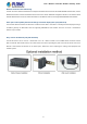
User’s Manual of MG-11x Modbus Gateway Series 2.2.2 Wall-mount Installation Step 1: Please find the wall that can mount the Modbus Gateway Step 2: Screw two screws on the wall. Step 3: Hang the Modbus Gateway on the screws from the wall. Step 4: Refer to Chapter 2.1.5 Power Information on power supply to the Modbus Gateway . Before mounting the device to the wall, please check the location of the electrical outlet and the length of the Ethernet cable.
User’s Manual of MG-11x Modbus Gateway Series 2.2.3 Media Chassis Installation (MG-110/115A) To install the Modbus Gateway in a 10-inch or 19-inch standard rack, follow the instructions described below. Step 1: Place your Modbus Gateway on a hard flat surface, with the front panel positioned towards your front side. Step 2: Carefully slide in the module until it is fully and firmly fitted into the slot of the chassis; the Power LED of the Modbus Gateway will turn ON.
User’s Manual of MG-11x Modbus Gateway Series Step 3: Check whether the DIN rail is tightly on the track. You must use the screws supplied with the mounting brackets. Damage caused to the parts by using incorrect screws would invalidate your warranty.
User’s Manual of MG-11x Modbus Gateway Series 3. MODBUS GATEWAY MANAGEMENT This chapter covers the following topics as to how to manage the Modbus Gateway: Requirements Web Management Remote Management PLANET Smart Discovery Utility MB VCOM Utility 3.1 Requirements Workstations running Windows 2000/XP, 2003, Vista/7/8/10, 2008, Mac OS 9 or later, or Linux, UNIX , or other platforms compatible with TCP/IP protocols.
User’s Manual of MG-11x Modbus Gateway Series 3.2 Web Management The Modbus Gateway offers management features that allow users to manage the Modbus Gateway from anywhere on the network through a standard browser such as Microsoft Internet Explorer. After you set up your IP address for the switch, you can access the Modbus Gateway's Web interface applications directly in your Web browser by entering the IP address of the Modbus Gateway. For example, the default IP address of the Modbus Gateway is 192.168.
User’s Manual of MG-11x Modbus Gateway Series 3. After entering the password, the main screen appears as shown in Figure 3-2-3. Figure 3-2-3: Web Main Screen of Modbus Gateway 4. The Main Menu in the middle of the Web page lets you access all the functions and statuses. It appears as shown in Figure 3-2-4. Figure 3-2-4: Main menu Now, you can use the Web management interface to continue the Modbus Gateway management. Please refer to the user manual for more. 1.
User’s Manual of MG-11x Modbus Gateway Series 3.3 Remote Management The Modbus Gateway also supports Telnet for remote management. You can use Telnet to open a terminal session over one of the Ethernet ports. The Modbus Gateway asks for user name and password for remote login when using Telnet; please use the following default IP address, username and password for the first-time login. Default IP Address: 192.168.0.
User’s Manual of MG-11x Modbus Gateway Series 3.4 PLANET Smart Discovery Utility For easily listing the Modbus Gateway in your Ethernet environment, the Planet Smart Discovery Utility is an ideal solution. The following installation instructions are to guide you to running the Planet Smart Discovery Utility. 1. Download the Planet Smart Discovery Utility from the administrator PC. 2. Run this utility as the following screen appears.
User’s Manual of MG-11x Modbus Gateway Series 2. After setup is completed, press the “Update Device”, “Update Multi” or “Update All” button to take effect. The functions of the 3 buttons above are shown below: Update Device: Use current setting on one single device. Update Multi: Use current setting on multi-devices. Update All: Use current setting on whole devices in the list. The same functions mentioned above also can be found in “Option” tools bar. 3.
User’s Manual of MG-11x Modbus Gateway Series 3.5 Getting Started with MB VCOM Utility With MB VCOM Utility, you can easily search one or multiple MG-110 or MG-115A Modbus Gateway over the network from a remote location. 3.5.1 Installation of MB VCOM Utility The MG-110/MG-115A MB VCOM Utility can be downloaded from PLANET Web site. Please locate and run the setup program “mbgsetup.exe” and follow the on-screen instructions. download link: https://www.planet.com.
User’s Manual of MG-11x Modbus Gateway Series 34
User’s Manual of MG-11x Modbus Gateway Series 4. WEB CONFIGURATION This section introduces the configuration and functions of the Web-based management from Modbus Gateway. About Web-based Management The Modbus Gateway offers management features that allow users to manage the Modbus Gateway from anywhere on the network through a standard browser such as Microsoft Internet Explorer. The Web-based Management supports Internet Explorer 7.0.
User’s Manual of MG-11x Modbus Gateway Series 2. When the following login screen appears, please enter the default username "admin" with password “admin” (or the username/password you have changed via console) to log in the main screen of Modbus Gateway. The login screen in Figure 4-1-2 appears. Figure 4-1-2: Login Screen 3. After a successful login, the main screen appears as shown in Figure 4-1-3 below.
User’s Manual of MG-11x Modbus Gateway Series 4.1 Main Web Page The Modbus Gateway provides a Web-based browser interface for configuring and managing it. This interface allows you to access the Modbus Gateway using the Web browser of your choice. The main web page is shown in Figure 4-1-4 Figure 4-1-4: Web Main Page Main Menu Via the Web Management, the administrator can set up the Modbus Gateway by selecting the functions that are listed in the Main Function. The screen in Figure 4-1-5 appears.
User’s Manual of MG-11x Modbus Gateway Series 4.2 System Use the System menu items to display and configure basic administrative details of the Modbus Gateway. Under the System, the following topics are provided to configure and view the system information. This section has the following items: System The Modbus Gateway system information is provided here. Port This page displays status of each port. Device Configure device name and syslog server on this page.
User’s Manual of MG-11x Modbus Gateway Series IPv4 Configuration Object Description • IP Configuration The status of IPv4 configuration. • IP Address The current IPv4 address of the device. • Subnet Mask The current IPv4 subnet mask of the device. • Gateway The current IPv4 gateway of the device. • Primary DNS The current first DNS server of the device. • Second DNS The current second DNS server of the device. • MAC Address Specifies the device MAC address.
User’s Manual of MG-11x Modbus Gateway Series 4.2.2 Port This Port page displays the status of each port, including operation mode and serial settings. The screen in Figure 4-2-2 appears. Figure 4-2-2: Port Status Page Screenshot The following column shows the Port statuses: Object Description • No. The serial number (No.) indicates port number. It can be directly linked to the corresponding page settings. • Operation Mode The current operation mode of Modbus Gateway.
User’s Manual of MG-11x Modbus Gateway Series 4.2.3 Device This page provides configuration of device name and syslog server. The screen in Figure 4-2-3 appears. Figure 4-2-3: Device Setup Page Screenshot The page includes the following fields: Object Description • Server Name To configure the name of server. The default value is Server. • Syslog Server To configure IP address of syslog server.
User’s Manual of MG-11x Modbus Gateway Series 4.2.5 Console This page is to configure management methods for web and remote console. The screen in Figure 4-2-5 appears. Figure 4-2-5: Console Setup Page Screenshot The page includes the following fields: Object Description • Web Console To enable or disable access to the web console. The default is Enable. • Remote Console To enable or disable access to the remote console. The default is Enable.
User’s Manual of MG-11x Modbus Gateway Series The page includes the following fields: Object Description • Enable Mail Alert To Enable SMTP function. The default value is “Disable”. • SMTP Server Set port number of SMTP service. The default number is “25”. • SMTP Server Port Type the SMTP server name or the IP address of the SMTP server address. • SMTP Login Username: Enter your login name for the SMTP Server. Information Password: Enter your password for the SMTP Server.
User’s Manual of MG-11x Modbus Gateway Series 4.3 Accessible IP This page provides the specified IP address to connect with Modbus Gateway. When the list of accessible IP is enabled, only IP address in the list can connect to device. When the function is disabled, there is no such restriction. The list allows user to configure up to four IP groups. The accessible IP setup screen in Figure 4-3-1 appears.
User’s Manual of MG-11x Modbus Gateway Series 4.4 Network This page allows the user to configure IPv4 or IPv6 address. The IP configuration screen in Figure 4-4-1 appears. Figure 4-4-1: IP Configuration Page Screenshot The page includes the following fields: IPv4 Object Description • IP Configuration Configure static or DHCP to get IPv4 address. The default value is static.
User’s Manual of MG-11x Modbus Gateway Series 4.5 Modbus Gateway The following figure shows port settings. Note that these settings need to match the parameters on serial port of the Modbus device. Each parameter is described in details in the following section. The port configuration screen in Figure 4-5-1 appears. Figure 4-5-1: Port Setup Page Screenshot 4.5.1 Serial setup The serial setup screen is shown in Figure 4-5-2.
User’s Manual of MG-11x Modbus Gateway Series • Interface • Flow Control Even Odd None Space Mark The device server supports three interfaces. The default value is RS-232. RS-232 RS-422 RS-485 2-Wire RS-485 4-Wire The method is used to suspend and resume data transmission to ensure that data is not lost. It supports four methods and default value is none.
User’s Manual of MG-11x Modbus Gateway Series Figure 4-5-4: Disable Mode Screenshot Buttons : Click to apply port config changes. When applying any configuration changes of Modbus Gateway, it’s required to save changed configuration and reboot system. Therefore the new configuration will be applied after rebooting. 4.5.2.2 RTU Slave mode This function allows the users to use Modbus TCP master device and Modbus RTU device to achieve communication.
User’s Manual of MG-11x Modbus Gateway Series Figure 4-5-6: RTU Slave Mode Screenshot 4.5.2.3 RTU Master mode This function allows the users to use Modbus RTU master device and Modbus TCP device to achieve communication. The operation mode of the Industrial Modbus Gateway is set to RTU Master. The serial telnet mode topology in Figure 4-5-7 appears. Figure 4-5-7: RTU Master Mode Topology The serial Telnet mode screenshot in Figure 4-5-8 appears. Figure 4-5-8: RTU Master Mode Screenshot 4.5.2.
User’s Manual of MG-11x Modbus Gateway Series Figure 4-5-10: ASCII Slave Mode Screenshot 4.5.2.5 ASCII Master mode This function allows the users to use Modbus ASCII master device and Modbus TCP device to achieve communication. The operation mode of the Industrial Modbus Gateway is set to ASCII Master. The TCP client mode topology in Figure 4-5-11 appears. Figure 4-5-11: ASCII Master Mode Topology The TCP client mode screenshot in Figure 4-5-12 appears. Figure 4-5-12: ASCII Master Mode Screenshot 4.5.
User’s Manual of MG-11x Modbus Gateway Series 4.5.4 Modbus Config 4.5.4.1 Router The Modbus Gateway support four Modbus masters in each serial port which can communicate with the Modbus slave devices. It can be connected to a serial port by IP address or TCP port. The screen in Figure 4-5-14 appears. Figure 4-5-14: Router Status Page Screenshot For example, IP address 192.168.0.60 is set and assigned to serial port 1.
User’s Manual of MG-11x Modbus Gateway Series of transmission. The default is 1. • Data Bits Indicates the number of the bits in a transmitted data package. The allowed value is 5,6,7,8 and default value is 8. 4.5.4.2 Mapping The ID Mapping Setup is a routing mechanism for gateway. It can follow routing rule on this table to transfer Modbus request to the specific serial port or TCP server that connects the Modbus slave device. The screen in Figure 4-5-16 appears.
User’s Manual of MG-11x Modbus Gateway Series Basic setting A Modbus device with slave ID 1 can be set to be connected to serial port 1 as shown in Figure 4-5-18 Figure 4-5-18: Basic setting of Mapping Screenshot Auto Device Routing It’s a mechanism that will help you find where It is and get routed correctly on serial port. So users don’t need to set the rule manually. If the Auto Device Routing is enabled, it will clear Slave ID Mapping value of the rule with serial port automatically.
User’s Manual of MG-11x Modbus Gateway Series 4.5.4.3 Parameters This function allows setting the value for serial port COM configuration. Press the “Apply” button to set the value and the screen in Figure 4-5-19 appears Figure 4-5-19: Parameters Setup Page Screenshot The page includes the following fields: Object Description • Initial Delay You can make the IP218 wait for some Modbus slave devices may take more time to boot up.
User’s Manual of MG-11x Modbus Gateway Series Figure 4-5-20: Master Setup Page Screenshot 4.5.5.2 TCP It is the same as priority master shown above, it means the request from port 1024 will be high priority. The screen in Figure 4-5-21 appears. Figure 4-5-21: TCP Setup Page Screenshot 4.5.5.3 Request The command type can also be made a priority request. Like the above, as requested by slave ID 3, function code 3 and data 00 00 00 03 will be high priority. The screen in Figure 4-5-22 appears.
User’s Manual of MG-11x Modbus Gateway Series 4.6 SNMP Setup Use the Port Menu to display or configure the Modbus Gateway's ports. This section includes the page that displays current port configurations. Ports can also be configured here. The Port Configuration screen in Figure 4-6-1 appears. Figure 4-6-1: SNMP Setup page Screenshot The page includes the following fields: Object Description • SNMP Active Indicates the SNMP mode operation.
User’s Manual of MG-11x Modbus Gateway Series 4.7 Maintenance Use the Port Menu to display or configure the Modbus Gateway's ports. This section includes the page that displays current port configurations. Ports can also be configured here. 4.7.1 Change Password After logging in to the Modbus Gateway, user can make changes from the "Change Password" page. The Change Password screen in Figure 4-7-1 appears.
User’s Manual of MG-11x Modbus Gateway Series 4.7.3 Firmware Update This page facilitates an update of the firmware controlling the switch. The Firmware Update screen in Figure 4-7-4 appears. Figure 4-7-4: Firmware Update Page Screenshot To open Firmware Update screen, perform the following: 1. Click Maintenance -> Firmware Update. 2. The Firmware Update screen is displayed as in Figure 4-7-4. 3. Click the “ 4. Select on the firmware and then click “ 5.
User’s Manual of MG-11x Modbus Gateway Series 4.8 Save and Restart When applying any configuration changes of Modbus Gateway, it’s required to save changed configuration and reboot system. Therefore the new configuration will be applied after rebooting. The Save and Restart screen in Figure 4-8-1 appears. Figure 4-8-1 : Save and Restart Page Screenshot Buttons : Click to save changes and restart system.
User’s Manual of MG-11x Modbus Gateway Series 5. SOFTWARE MB VCOM UTILITY The “MB VCOM” Administration Suite provides you search function to find your MG-11x Modbus Gateway from a remote location. With MB VCOM Utility, you can easily install and search your MG-11x Modbus Gateway over the network. You can also run MB VCOM Utility from one location to manage multiple device servers. The setup program will be named mbgsetup.exe. 5.1 Installing the VCOM Utility 1.
User’s Manual of MG-11x Modbus Gateway Series Figure 5-1-2 : Installing location 3. The setup wizard will show the progress of the installation and status as shown in Figure 5-1-3.
User’s Manual of MG-11x Modbus Gateway Series 4. Click Finish to successfully complete installation of VCOM software.as shown in Figure 5-1-4. Figure 5-1-4 : Installation Finished 5. Restart computer as shown in Figure 5-1-5.
User’s Manual of MG-11x Modbus Gateway Series 5.2 Search Devices 1. First click "Add Device" and then click "Search" if device has access to network, as shown in Figure 5-2-1. Figure 5-2-1 : Searching Devices 2. After adding an MG-110 device as shown in Figure Figure 5-2-2. When you close searching window, it will add device automatically on main window. If you want to modify MG-110, please click “Open in Browser” to modify on web page.
User’s Manual of MG-11x Modbus Gateway Series 5.3 COM Port Mapping This function should be set as VCOM mode on the Modbus Gateway. VCOM software will create the corresponding virtual COM ports for com port mapping as shown in Figure 5-3-1. Figure 5-3-1 : VCOM software Add Virtual COM port 1. Click "Search" to search the network for device servers. 2. Once a server has been found, select it to add it to the COM mapping list and Click "OK" to take effect as shown in Figure 5-3-2.
User’s Manual of MG-11x Modbus Gateway Series Figure 5-3-3 : Virtual COM Ports 4. From the Windows Device Manager, four COM Ports are added to the device list as shown in Figure 5-3-4.