0/100/1000Mbps Intelligent Ethernet Switch MGSW-2402 User’s Manaul
Trademarks Copyright PLANET Technology Corp. 2002. Contents subject to revision without prior notice. PLANET is a registered trademark of PLANET Technology Corp. All other trademarks belong to their respective owners. FCC Warning This equipment has been tested and found to comply with the limits for a Class A digital device, pursuant to Part 15 of the FCC Rules.
TABLE OF CONTENTS 1. INTROUCTION........................................................................................................................................4 1.1 CHECKLIST ...............................................................................................................................4 1.2 ABOUT THE SWITCH ..................................................................................................................4 1.3 FEATURES .................................................
1. INTROUCTION 1.1 Checklist Check the contents of your package for following parts: MGSW-2402. User's manual CD. Power cord. 19” rack mount kit. RS-232 cable. Quick Installation Guide. If any of these pieces are missing or damaged, please contact your dealer immediately, if possible, retain the carton including the original packing material, and use them against to repack the product in case there is a need to return it to us for repair. 1.
Internal power supply Auto MDI/ MDI-X on each port Network management configuration: − Web-based management − Console and Telnet Configuration − SNMP network management − IEEE 802.1Q Tagging VLAN ( 256 VLAN Group ) − IEEE 802.1D Spanning Tree Protocol ( STP ) − Port Trunking supported − IGMP and Sniffer ( Port Mirroring ) supported − Port Priority - 802.
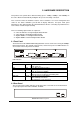
2. HARDWARE DESCRIPTION This product series provide three different running speed – 10Mbps, 100Mbps, and 1000Mbps in the same switch and automatically distinguish the speed of incoming connection. This section describes the hardware features of these Switches. For easier management and control of the switch, familiarize yourself with its display indicators, and ports. Front panel illustrations in this chapter display the unit LED indicators.
Power Notice: 1. The device is a power-required device, it means, it will not work till it is powered. If your networks should active all the time, please consider using UPS (Uninterrupted Power Supply) for your device. It will prevent you from network data loss or network downtime. 2. In some area, installing a surge suppression device may also help to protect your switch from being damaged by unregulated surge or current to the Switch or the power adapter. 2.3 Hardware Installation 2.3.
3.WEB-BASED MANAGEMENT This chapter describes how to manage the Switch through the at-hand browser like Internet Browser IE 4.0 or Netscape Communicator 4.x or above. Please check the JAVA applet is enabled in your browser’s option or preference. 3.1 Configuration The management function of this interface runs as an unsigned Java applet. As a result, your browser’s security setting should be set as following: • For Netscape 4 or later: 1. 2. 3. 4. 5. 6. • For Internet Explorer 4: 1. 2. 3. 4. 5. 6. 7. 8.
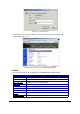
Figure 3-1 : Password Screen The default user name and password is "root". After the password is entered you will see the main menu screen. Figure 3-2: The start up screen of MGSW-2402 Web Page 3.3 Home The Home page displays the configuration of the MGSW-2402 Intelligent Switch. System Name An administratively-assigned name of the managed unit System Location The physical location of this managed unit System Contact The contact person for this managed unit.
3.4 Modules Modules page shows the modules that have installed into the MGSW-2402-Slot Intelligent Switch. There are fixed 24x 10/100 Base-TX ports in Module 0, and another 2 slot ( module 1 and module 2 ) are used for expansion. In the following example, 1-port Gigabit 1000Base-SX ( LX ) Fiber Module, and 4-port 100Base-FX (ST) Fiber Module are installed into the Switch. Figure 3-3 The Modules Page 3.
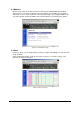
3.6 Statistics The Statistic page displays the detailed information about each port. You can compare and evaluate throughput or other port parameters. All screen data is updated automatically and you can also update the data manually. Figure 3-5 The Statistics Page 3.7 VLAN A VLAN ( Virtual LAN ) is a group of switch ports designated by the switch as belonging to the same broadcast domain.
Figure 3-6 The VLAN Page In the VLAN management window, you will see 2 VLANs in the page.
You can add, edit and remove port members of each trunk and then press "Apply" button after you have finished configuring the trunks you need. ( Note: Make sure trunking ports are in the same VLAN group. ) 3.9 STP (Spanning Tree Protocol) Spanning tree is a link management protocol that provides path redundancy while preventing undesirable loops in the network. For Layer 2 Ethernet network to function properly, only one active path must exist between two stations.
3.10 Port Security Port Security allows you to restrict specific MAC addresses to reside in some port. For example, a dummy hub is attached to some port for extension, and you just only allow 2 users to access this port at the same time, you can use the port security window to set the parameters. Figure 3-9. The Port Security page To restrict the number of MAC address to reside in a port, you must do the following : Click the “ Enable “ checkbox for that port.
Figure 3-10. Port Priority – 802.1p page Programmable Mapping of 802.1p to Internal Priority The received packets with 802.1q tag are assigned priority according to a flexible and programmable mapping of the 802.1p user-priority tag (3 bits, value from 0 to 7) to the internal priority queue. The default is to assign a packet to high priority queue when the 802.1p user-priority tag is 4 to 7, and to low priority queue when the 802.1p user-priority tag is 0 to 3.
3.13 IGMP Multicasting is used to support real-time applications such as video conferencing or streaming audio. IGMP ( Internet Group Management Protocol ) allow you to query for any attached hosts who want to receive a specific multicast service. The switch looks up the IP Multicast Group used for this service and adds any port which received a similar request to that group.
Static addresses are manually entered into the Static Address Table. 1. Enter the MAC address in the MAC Address field (ex. 00-00-00-00-00-01) and VLAN ID (default is 1) 2. 3. 4. Select the Module and Port you want to associate with this entry with from the Port drop-down box. Click <
3-15 The Port Mirroring page If you want to monitor all receive and transmit packets of one port. You can do the following: Choose the monitored port in " Mirror Source Port " choice box in the corresponding mirror source module. Only one port can be monitored in one module at the same time. Choose the corresponding target module, port in "Mirror Target Module" and "Mirror Target Port" choice box. Click the corresponding "Enabled" check box. Press "Apply" button 3.
Enter the same password in "Password" and "Confirm Password" edit box Press the "Apply" button You should reboot system to let your settings take effect if you have changed one of the IP address, subnet mask and default gateway. 3.18 SNMP You can manage the Switch using third-party’s SNMP ( Simple Network Management Protocol ) agent. Access rights to the SNMP agent are controlled by community strings.
Figure 3-18 Save & Reboot page 3.20 Upgrade You can on-line upgrade the firmware of the managed unit. The following steps is needed to upgrade the firmware: Use HTTP or FTP to download the new version firmware from our website. Enter password in the "Password" edit box. Enter the file downloaded in the "File Path" edit box. (You can use "Browse" button to select the file.) Press the "Upgrade" button.
- 21 -
4 CONSOLE INTERFACE 4.1 CONNECT TO PC RS-232 serial cable Prepare a RS-232 serial cable. Attach the 9-pin female connector to the male connector on the switch. Plug the other side of this cable to your PC. Hyper Terminal In Windows 95/98/2000/XP,launch “HyperTerminal”, create a new connection, and adjust settings as below: 4.2 Main Menu The main menu displays all the sub-menus that are available. Striking Enter, at a highlighted option, will confirm the choice of the specified sub-menu.
Figure 4-1 The Main Menu of Console Management 4.2.1. Device settings This menu contains system parameters to display and configure the switch to your network.
• Speed/Duplex: allow set Auto- negotiation,100Mbps-full/half duplex,10Mbps-full/half duplex • Flow Control: allow enable or disable flow control on each port • Back Pressure: allow enable or disable Back Pressure on each port • VLAN Tagged: allow enable or disable VLAN Tagged on each port • Default VLAN ID: allow set VLAN ID 1~4095 on each port • Note: set and display the information of each port • Quit: back to previous menu Figure 4-3: Port Settings 4.2.3.
Figure 4-5: Spanning Tree 4.2.5 Broadcast Storm Filter This menu contains three items to enable or disable Broadcast Storm Filter: ● Enable ● Disable ● Quit Figure 4-6: Broadcast Storm Filter 4.2.6.
4.2.7. VLAN Mode (2 modes) This menu contains two items for 2 VLAN mode selection: ● VLAN is valid for all packets Disable ● VLAN is valid for broadcast and multicast packets, not for unicast packets. ● Quit Figure 4-8: VLAN Mode( 2 modes) 4.2.8. VLAN for CPU (2 VLANs) This menu contains two items for 2 VLANs for CPU: ● ● ● Current first VLAN for CPU: VLAN ID 1Current second VLAN for CPU: None Quit Figure 4-9: VLAN for CPU( 2 VLANs) 4.2.
4.2.9.1 Secure IP for Telnet: disable allow any PC login in MGSW-2402 by Telnet , enable allow the PC of secure IP login in MGSW-2402. 4.2.9.2 Secure IP for HTTP: disable allow any PC login in MGSW-2402 by HTTP, enable allow PC of secure IP login in MGSW-2402. 4.2.9.3 Secure IP 1.2.3.4: allow to set 4 Secure IP address of 4 PCs Figure 4-10: Secure IP for Telnet and HTTP 4.2.10. Save Current Settings This menu provide save current settings of this Switch. Figure 4-11: Save Current Settings 4.2.
Figure 4-12: Factory Default Settings & Reboot System 4.2.12 Reboot System This menu provide reboot the Switch Figure 4-13: Reboot System 4.2.
5 SOFTWARE UPGRADE PROCEDURE The application software is field upgradable. The upgrade procedure and the required equipment is described in the following section. Note that once the system is up, it is controlled by an executing application image residing in the flash memory. No software upgrade is possible during this mode. The upgrade can only be done when the system is resetting.
APPENDIX A NETWORKING CONNECTION When attaching an end-station to the device, a standard straight-through CAT5 cable may be used, even when the end-station is attached via a patch panel. However, when attaching another switch or attaching workstations via hubs, a crossover cable will need to be used. Please see the following wire diagrams for examples of both cable types.
APPENDIX B TECHNICAL SPECIFICATIONS Standard IEEE802.3, IEEE802.3u, IEEE802.3z, IEEE802.3ab,IEEE802.1Q,IEEE802.