
User's Manual
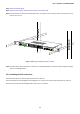
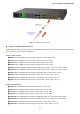
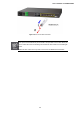

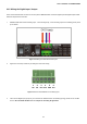
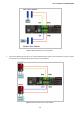
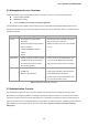
Table Of Contents
- 1. INTRODUTION
- 2. INSTALLATION
- 3. SWITCH MANAGEMENT
- 4. WEB CONFIGURATION
- 4.1 Main Web Page
- 4.2 System
- 4.2.1 System Information
- 4.2.2 IP Configuration
- 4.2.3 IPv6 Configuration
- 4.2.4 Users Configuration
- 4.2.5 Users Privilege Levels
- 4.2.6 NTP Configuration
- 4.2.7 UPnP Configuration
- 4.2.8 DHCP Relay
- 4.2.9 DHCP Relay Statistics
- 4.2.10 CPU Load
- 4.2.11 System Log
- 4.2.12 Detailed Log
- 4.2.13 Remote Syslog
- 4.2.14 SMTP Configure
- 4.2.15 Web Firmware Upgrade
- 4.2.16 TFTP Firmware Upgrade
- 4.2.17 Configuration Backup
- 4.2.18 Configuration Upload
- 4.2.19 Digital input/output
- 4.2.20 Fault Alarm
- 4.2.21 Factory Default
- 4.2.22 System Reboot
- 4.3 Simple Network Management Protocol
- 4.4 Port Management
- 4.5 Link Aggregation
- 4.6 VLAN
- 4.6.1 VLAN Overview
- 4.6.2 IEEE 802.1Q VLAN
- 4.6.3 VLAN Basic Information
- 4.6.4 VLAN Port Configuration
- 4.6.5 VLAN Membership Configuration
- 4.6.6 VLAN Membership Status for User Static
- 4.6.7 VLAN Port Status for User Static
- 4.6.8 Port Isolation Configuration
- 4.6.9 Private VLAN Membership Configuration
- 4.6.10 VLAN setting example:
- 4.7 Spanning Tree Protocol
- 4.8 Multicast
- 4.9 Quality of Service
- 4.10 Access Control Lists
- 4.11 Authentication
- 4.11.1 Understanding IEEE 802.1X Port-Based Authentication
- 4.11.2 Authentication Configuration
- 4.11.3 Network Access Server Configuration
- 4.11.4 Network Access Overview
- 4.11.5 Network Access Statistics
- 4.11.6 Authentication Server Configuration
- 4.11.7 RADIUS Overview
- 4.11.8 RADIUS Details
- 4.11.9 Windows Platform RADIUS Server Configuration
- 4.11.10 802.1X Client Configuration
- 4.12 Security
- 4.12.1 Port Limit Control
- 4.12.2 Access Management
- 4.12.3 Access Management Statistics
- 4.12.4 HTTPs
- 4.12.5 SSH
- 4.12.6 Port Security Status
- 4.12.7 Port Security Detail
- 4.12.8 DHCP Snooping
- 4.12.9 DHCP Snooping Statistics
- 4.12.10 IP Source Guard Configuration
- 4.12.11 IP Source Guard Static Table
- 4.12.12 ARP Inspection
- 4.12.13 ARP Inspection Static Table
- 4.13 Address Table
- 4.14 LLDP
- 4.15 Network Diagnostics
- 5. COMMAND LINE INTERFACE
- 6. Command Line Mode
- 6.1 System Command
- 6.2 IP Command
- 6.3 Port Management Command
- 6.4 MAC Address Table Command
- 6.5 VLAN Configuration Command
- 6.6 Private VLAN Configuration Command
- 6.7 Security Command
- Security Switch User Configuration
- Security Switch User Add
- Security Switch User Delete
- Security Switch Privilege Level Configuration
- Security Switch Privilege Level Group
- Security Switch Privilege Level Current
- Security Switch Auth Configuration
- Security Switch Auth Method
- Security Switch SSH Configuration
- Security Switch SSH Mode
- Security Switch HTTPs Configuration
- Security Switch HTTPs Mode
- Security Switch HTTPs Redirect
- Security Switch Access Configuration
- Security Switch Access Mode
- Security Switch Access Add
- Security Switch Access IPv6 Add
- Security Switch Access Delete
- Security Switch Access Look up
- Security Switch Access Clear
- Security Switch Access Statistics
- Security Switch SNMP Configuration
- Security Switch SNMP Mode
- Security Switch SNMP Version
- Security Switch SNMP Read Community
- Security Switch SNMP Write Community
- Security Switch SNMP Trap Mode
- Security Switch SNMP Trap Version
- Security Switch SNMP Trap Community
- Security Switch SNMP Trap Destination
- Security Switch SNMP Trap IPv6 Destination
- Security Switch SNMP Trap Authentication Failure
- Security Switch SNMP Trap Link-up
- Security Switch SNMP Trap Inform Mode
- Security Switch SNMP Trap Inform Timeout
- Security Switch SNMP Trap Inform Retry Times
- Security Switch SNMP Trap Probe Security Engine ID
- Security Switch SNMP Trap Security Engine ID
- Security Switch SNMP Trap Security Name
- Security Switch SNMP Engine ID
- Security Switch SNMP Community Add
- Security Switch SNMP Community Delete
- Security Switch SNMP Community Look up
- Security Switch SNMP User Add
- Security Switch SNMP User Delete
- Security Switch SNMP User Changekey
- Security Switch SNMP User Look up
- Security Switch SNMP Group Add
- Security Switch SNMP Group Delete
- Security Switch SNMP Group Look up
- Security Switch SNMP View Add
- Security Switch SNMP View Delete
- Security Switch SNMP View Look up
- Security Switch SNMP Access Add
- Security Switch SNMP Access Delete
- Security Switch SNMP Access Look up
- Security Network Psec Switch
- Security Network Psec Port
- Security Network Limit Configuration
- Security Network Limit Mode
- Security Network Limit Aging
- Security Network Limit Agetime
- Security Network Limit Port
- Security Network Limit Limit
- Security Network Limit Action
- Security Network Limit Reopen
- Security Network NAS Configuration
- Security Network NAS Mode
- Security Network NAS State
- Security Network NAS Reauthentication
- Security Network NAS ReauthPeriod
- Security Network NAS EapolTimeout
- Security Network NAS Agetime
- Security Network NAS Holdtime
- Security Network NAS RADIUS_QoS
- Security Network NAS RADIUS_VLAN
- Security Network NAS Guest_VLAN
- Security Network NAS Authenticate
- Security Network NAS Statistics
- Security Network ACL Configuration
- Security Network ACL Action
- Security Network ACL Policy
- Security Network ACL Rate
- Security Network ACL Add
- Security Network ACL Delete
- Security Network ACL Look up
- Security Network ACL Clear
- Security Network ACL Status
- Security Network DHCP Relay Configuration
- Security Network DHCP Relay Mode
- Security Network DHCP Relay Server
- Security Network DHCP Relay Information Mode
- Security Network DHCP Relay Information Policy
- Security Network DHCP Relay Statistics
- Security Network DHCP Snooping Configuration
- Security Network DHCP Snooping Mode
- Security Network DHCP Snooping Port Mode
- Security Network DHCP Snooping Statistics
- Security Network IP Source Guard Configuration
- Security Network IP Source Guard Mode
- Security Network IP Source Guard Port Mode
- Security Network IP Source Guard Limit
- Security Network IP Source Guard Entry
- Security Network IP Source Guard Status
- Security Network ARP Inspection Configuration
- Security Network ARP Inspection Mode
- Security Network ARP Inspection Port Mode
- Security Network ARP Inspection Entry
- Security Network ARP Inspection Status
- Security AAA Configuration
- Security AAA Timeout
- Security AAA Deadtime
- Security AAA RADIUS
- Security AAA ACCT_RADIUS
- Security AAA TACACS+
- Security AAA Statistics
- 6.8 Spanning Tree Protocol Command
- STP Configuration
- STP Version
- STP Tx Hold
- STP MaxHops
- STP MaxAge
- STP FwdDelay
- STP CName
- STP BPDU Filter
- STP BPDU Guard
- STP Recovery
- STP Status
- STP MSTI Priority
- STP MSTI Map
- STP MSTI Add
- STP Port Configuration
- STP Port Mode
- STP Port Edge
- STP Port AutoEdge
- STP Port P2P
- STP Port RestrictedRole
- STP Port RestrictedTcn
- STP Port bpduGuard
- STP Port Statistic
- STP Port Mcheck
- STP MSTI Port Configuration
- STP MSTI Port Cost
- STP MSTI Port Priority
- 6.9 Multicast Configuration Command
- 6.10 Link Aggregation Command
- 6.11 Link Aggregation Control Protocol Command
- 6.12 LLDP Command
- 6.13 LLDPMED Command
- 6.14 Quality of Service Command
- 6.15 Mirror Command
- 6.16 Configuration Command
- 6.17 Firmware Command
- 6.18 UPnP Command
- 6.19 MVR Command
- 6.20 Voice VLAN Command
- 6.21 SMTP Command
- 6.22 Show Command
- Show ACL Configuration
- Show Link Aggregation Configuration
- Show IGMP Configuration
- Show IP Configuration
- Show LACP Configuration
- Show LLDP Configuration
- Show MAC Configuration
- Show Mirror Configuration
- Show PoE Configuration
- Show Port Configuration
- Show Private VLAN Configuration
- Show QoS Configuration
- Show SNMP Configuration
- Show System Configuration
- Show VLAN Configuration
- Show STP Configuration
- 6.23 DIDO Command
- 7. SWITCH OPERATION
- 8. TROUBLE SHOOTING
- APPENDEX A
- APPENDEX B : GLOSSARY
- EC Declaration of Conformity

User’s Manual of MGSW-24160F
2.2.5 Wiring the Digital Input / Output
The 6-contact terminal block connector on the rear panel of MGSW-24160F is used for Digital Input and Digital Output. Please
follow the steps below to insert wire.
1. MGSW-24160F offers two DI and DO groups. 1 and 2 are DI groups, 3 and 4 are DO groups and 5 is GND (ground).The 6
pin is useless.
Figure 2-11 Wiring the Redundant Power Inputs
2. Tighten the wire-clamp screws for preventing the wires from loosing.
1 2 3 4 5 6
DI0 DI1 DO0 DO1 GND N/A
Figure 2-12 6-Pin Terminal Block DI / DO Wiring Input
3. There are two Digital Input groups for you to monitor two different devices. As following topology shows how to wire DI0
and DI1. We use MGSW-24160F to be an example for describing DI application.
37