
User's Manual

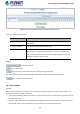
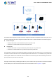
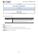
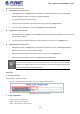
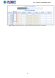
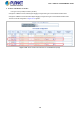
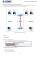

Table Of Contents
- 1. INTRODUCTION
- 2. INSTALLATION
- 3. SWITCH MANAGEMENT
- 4. WEB CONFIGURATION
- 4.1 Main Web Page
- 4.2 System
- 4.2.1 System Information
- 4.2.2 IP Configuration
- 4.2.3 IP Status
- 4.2.4 Users Configuration
- 4.2.5 Privilege Levels
- 4.2.6 NTP Configuration
- 4.2.7 Time Configuration
- 4.2.8 UPnP
- 4.2.9 DHCP Relay
- 4.2.10 DHCP Relay Statistics
- 4.2.11 CPU Load
- 4.2.12 System Log
- 4.2.13 Detailed Log
- 4.2.14 Remote Syslog
- 4.2.15 SMTP Configuration
- 4.2.16 Digital Input/Output
- 4.2.17 Faulty Alarm
- 4.2.18 Web Firmware Upgrade
- 4.2.19 TFTP Firmware Upgrade
- 4.2.20 Save Startup Config
- 4.2.21 Configuration Download
- 4.2.22 Configuration Upload
- 4.2.23 Configuration Activate
- 4.2.24 Configuration Delete
- 4.2.25 Image Select
- 4.2.26 Factory Default
- 4.2.27 System Reboot
- 4.3 Simple Network Management Protocol
- 4.4 Port Management
- 4.5 Link Aggregation
- 4.6 VLAN
- 4.7 Spanning Tree Protocol
- 4.8 Multicast
- 4.8.1 IGMP Snooping
- 4.8.2 Profile Table
- 4.8.3 Address Entry
- 4.8.4 IGMP Snooping Configuration
- 4.8.5 IGMP Snooping VLAN Configuration
- 4.8.6 IGMP Group Port Group Filtering
- 4.8.7 IGMP Snooping Status
- 4.8.8 IGMP Group Information
- 4.8.9 IGMPv3 Information
- 4.8.10 MLD Snooping Configuration
- 4.8.11 MLD Snooping VLAN Configuration
- 4.8.12 MLD Snooping Port Group Filtering
- 4.8.13 MLD Snooping Status
- 4.8.14 MLD Group Information
- 4.8.15 MLDv2 Information
- 4.8.16 MVR (Multicaset VLAN Registration)
- 4.8.17 MVR Status
- 4.8.18 MVR Groups Information
- 4.8.19 MVR SFM Information
- 4.9 Quality of Service
- 4.9.1 Understand QOS
- 4.9.2 Port Policing
- 4.9.3 Port Shaping
- 4.9.4 Port Classification
- 4.9.5 Port Scheduler
- 4.9.6 Port Tag Remarking
- 4.9.7 Port DSCP
- 4.9.8 DSCP-Based QoS
- 4.9.9 DSCP Translation
- 4.9.10 DSCP Classification
- 4.9.11 QoS Control List
- 4.9.12 QoS Status
- 4.9.13 Storm Control Configuration
- 4.9.14 WRED
- 4.9.15 QoS Statistics
- 4.9.16 Voice VLAN Configuration
- 4.9.17 Voice VLAN OUI Table
- 4.10 Access Control Lists
- 4.11 Authentication
- 4.12 Security
- 4.12.1 Port Limit Control
- 4.12.2 Access Management
- 4.12.3 Access Management Statistics
- 4.12.4 HTTPs
- 4.12.5 SSH
- 4.12.6 Port Security Status
- 4.12.7 Port Security Detail
- 4.12.8 DHCP Snooping
- 4.12.9 DHCP Snooping Statistics
- 4.12.10 IP Source Guard Configuration
- 4.12.11 IP Source Guard Static Table
- 4.12.12 ARP Inspection
- 4.12.13 ARP Inspection Static Table
- 4.13 MAC Address Table
- 4.14 LLDP
- 4.15 Diagnostics
- 4.16 Loop Protection
- 4.17 RMON
- 4.18 PTP (MGSW-28240F Only)
- 4.19 Ring (For MGSD-10080F and MGSW-28240F)
- 5. SWITCH OPERATION
- 6. TROUBLESHOOTING
- APPENDIX A
- APPENDIX B: GLOSSARY
- EC Declaration of Conformity

User’s Manual of MGSW-MGSD Series
4.6.8.2 VLAN Trunking between two 802.1Q aware Switches
The most cases are used for “Uplink” to other switches. VLANs are separated at different switches, but they need to access
with other switches within the same VLAN group. The screen in Figure 4-6-12 appears.
Figure 4-6-12: VLAN Trunking Diagram
Setup steps
1. Add VLAN Group
Add two VLANs – VLAN 2 and VLAN 3
Type 1-3 in Allowed Access VLANs column, the 1-3 is including VLAN1 and 2 and 3.
Figure 4-6-13: Add VLAN 2 and VLAN 3
2. Assign VLAN Member and PVID for each port :
VLAN 2 : Port-1,Port-2 and Port-3
VLAN 3 : Port-4, Port-5 and Port-6
VLAN 1 : All other ports – Port-7~Port-48
139