
User's Manual
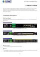
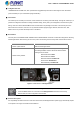
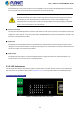
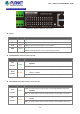
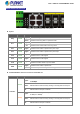


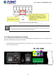
Table Of Contents
- 1. INTRODUCTION
- 2. INSTALLATION
- 3. SWITCH MANAGEMENT
- 4. WEB CONFIGURATION
- 4.1 Main Web Page
- 4.2 System
- 4.2.1 System Information
- 4.2.2 IP Configuration
- 4.2.3 IP Status
- 4.2.4 Users Configuration
- 4.2.5 Privilege Levels
- 4.2.6 NTP Configuration
- 4.2.7 Time Configuration
- 4.2.8 UPnP
- 4.2.9 DHCP Relay
- 4.2.10 DHCP Relay Statistics
- 4.2.11 CPU Load
- 4.2.12 System Log
- 4.2.13 Detailed Log
- 4.2.14 Remote Syslog
- 4.2.15 SMTP Configuration
- 4.2.16 Digital Input/Output
- 4.2.17 Faulty Alarm
- 4.2.18 Web Firmware Upgrade
- 4.2.19 TFTP Firmware Upgrade
- 4.2.20 Save Startup Config
- 4.2.21 Configuration Download
- 4.2.22 Configuration Upload
- 4.2.23 Configuration Activate
- 4.2.24 Configuration Delete
- 4.2.25 Image Select
- 4.2.26 Factory Default
- 4.2.27 System Reboot
- 4.3 Simple Network Management Protocol
- 4.4 Port Management
- 4.5 Link Aggregation
- 4.6 VLAN
- 4.7 Spanning Tree Protocol
- 4.8 Multicast
- 4.8.1 IGMP Snooping
- 4.8.2 Profile Table
- 4.8.3 Address Entry
- 4.8.4 IGMP Snooping Configuration
- 4.8.5 IGMP Snooping VLAN Configuration
- 4.8.6 IGMP Group Port Group Filtering
- 4.8.7 IGMP Snooping Status
- 4.8.8 IGMP Group Information
- 4.8.9 IGMPv3 Information
- 4.8.10 MLD Snooping Configuration
- 4.8.11 MLD Snooping VLAN Configuration
- 4.8.12 MLD Snooping Port Group Filtering
- 4.8.13 MLD Snooping Status
- 4.8.14 MLD Group Information
- 4.8.15 MLDv2 Information
- 4.8.16 MVR (Multicaset VLAN Registration)
- 4.8.17 MVR Status
- 4.8.18 MVR Groups Information
- 4.8.19 MVR SFM Information
- 4.9 Quality of Service
- 4.9.1 Understand QOS
- 4.9.2 Port Policing
- 4.9.3 Port Shaping
- 4.9.4 Port Classification
- 4.9.5 Port Scheduler
- 4.9.6 Port Tag Remarking
- 4.9.7 Port DSCP
- 4.9.8 DSCP-Based QoS
- 4.9.9 DSCP Translation
- 4.9.10 DSCP Classification
- 4.9.11 QoS Control List
- 4.9.12 QoS Status
- 4.9.13 Storm Control Configuration
- 4.9.14 WRED
- 4.9.15 QoS Statistics
- 4.9.16 Voice VLAN Configuration
- 4.9.17 Voice VLAN OUI Table
- 4.10 Access Control Lists
- 4.11 Authentication
- 4.12 Security
- 4.12.1 Port Limit Control
- 4.12.2 Access Management
- 4.12.3 Access Management Statistics
- 4.12.4 HTTPs
- 4.12.5 SSH
- 4.12.6 Port Security Status
- 4.12.7 Port Security Detail
- 4.12.8 DHCP Snooping
- 4.12.9 DHCP Snooping Statistics
- 4.12.10 IP Source Guard Configuration
- 4.12.11 IP Source Guard Static Table
- 4.12.12 ARP Inspection
- 4.12.13 ARP Inspection Static Table
- 4.13 MAC Address Table
- 4.14 LLDP
- 4.15 Diagnostics
- 4.16 Loop Protection
- 4.17 RMON
- 4.18 PTP (MGSW-28240F Only)
- 4.19 Ring (For MGSD-10080F and MGSW-28240F)
- 5. SWITCH OPERATION
- 6. TROUBLESHOOTING
- APPENDIX A
- APPENDIX B: GLOSSARY
- EC Declaration of Conformity

User’s Manual of MGSW-MGSD Series
2. INSTALLATION
This section describes the hardware features and installation of the Managed Switch on the desktop or rack mount. For easier
management and control of the Managed Switch, familiarize yourself with its display indicators, and ports. Front panel
illustrations in this chapter display the unit LED indicators. Before connecting any network device to the Managed Switch, please
read this chapter completely.
2.1 Hardware Descriptions
2.1.1 Front Panel
The front panel provides a simple interface monitoring the Managed Switch. Figures 2-1-1 to 2-1-3 show the front panel of the
Managed Switch.
MGSD-10080F Front Panel
Figure 2-1-1: MGSD-10080F Switch Front Panel
MGSW-24160F Front Panel
Figure 2-1-2: MGSW-24160F Switch Front Panel
MGSW-28240F Front Panel
Figure 2-1-3: MGSW-28240F Switch Front Panel
■ Gigabit TP interface
10/100/1000BASE-T Copper, RJ45 twisted-pair: Up to 100 meters.
■ SFP slot
100/1000BASE-X mini-GBIC slot, SFP (Small Factor Pluggable) transceiver module: From 550 meters to 2km (multi-mode
fiber), and up to 10/20/30/40/50/70/120 kilometers (single-mode fiber).
21