
User's Manual
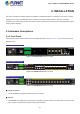
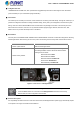
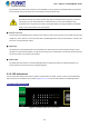
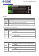


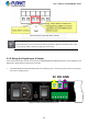
Table Of Contents
- 1. INTRODUCTION
- 2. INSTALLATION
- 3. SWITCH MANAGEMENT
- 4. WEB CONFIGURATION
- 4.1 Main Web Page
- 4.2 System
- 4.2.1 System Information
- 4.2.2 IP Configuration
- 4.2.3 IP Status
- 4.2.4 Users Configuration
- 4.2.5 Privilege Levels
- 4.2.6 NTP Configuration
- 4.2.7 Time Configuration
- 4.2.8 UPnP
- 4.2.9 DHCP Relay
- 4.2.10 DHCP Relay Statistics
- 4.2.11 CPU Load
- 4.2.12 System Log
- 4.2.13 Detailed Log
- 4.2.14 Remote Syslog
- 4.2.15 SMTP Configuration
- 4.2.16 Digital Input/Output
- 4.2.17 Faulty Alarm
- 4.2.18 Web Firmware Upgrade
- 4.2.19 TFTP Firmware Upgrade
- 4.2.20 Save Startup Config
- 4.2.21 Configuration Download
- 4.2.22 Configuration Upload
- 4.2.23 Configuration Activate
- 4.2.24 Configuration Delete
- 4.2.25 Image Select
- 4.2.26 Factory Default
- 4.2.27 System Reboot
- 4.3 Simple Network Management Protocol
- 4.4 Port Management
- 4.5 Link Aggregation
- 4.6 VLAN
- 4.7 Spanning Tree Protocol
- 4.8 Multicast
- 4.8.1 IGMP Snooping
- 4.8.2 Profile Table
- 4.8.3 Address Entry
- 4.8.4 IGMP Snooping Configuration
- 4.8.5 IGMP Snooping VLAN Configuration
- 4.8.6 IGMP Group Port Group Filtering
- 4.8.7 IGMP Snooping Status
- 4.8.8 IGMP Group Information
- 4.8.9 IGMPv3 Information
- 4.8.10 MLD Snooping Configuration
- 4.8.11 MLD Snooping VLAN Configuration
- 4.8.12 MLD Snooping Port Group Filtering
- 4.8.13 MLD Snooping Status
- 4.8.14 MLD Group Information
- 4.8.15 MLDv2 Information
- 4.8.16 MVR (Multicaset VLAN Registration)
- 4.8.17 MVR Status
- 4.8.18 MVR Groups Information
- 4.8.19 MVR SFM Information
- 4.9 Quality of Service
- 4.9.1 Understand QOS
- 4.9.2 Port Policing
- 4.9.3 Port Shaping
- 4.9.4 Port Classification
- 4.9.5 Port Scheduler
- 4.9.6 Port Tag Remarking
- 4.9.7 Port DSCP
- 4.9.8 DSCP-Based QoS
- 4.9.9 DSCP Translation
- 4.9.10 DSCP Classification
- 4.9.11 QoS Control List
- 4.9.12 QoS Status
- 4.9.13 Storm Control Configuration
- 4.9.14 WRED
- 4.9.15 QoS Statistics
- 4.9.16 Voice VLAN Configuration
- 4.9.17 Voice VLAN OUI Table
- 4.10 Access Control Lists
- 4.11 Authentication
- 4.12 Security
- 4.12.1 Port Limit Control
- 4.12.2 Access Management
- 4.12.3 Access Management Statistics
- 4.12.4 HTTPs
- 4.12.5 SSH
- 4.12.6 Port Security Status
- 4.12.7 Port Security Detail
- 4.12.8 DHCP Snooping
- 4.12.9 DHCP Snooping Statistics
- 4.12.10 IP Source Guard Configuration
- 4.12.11 IP Source Guard Static Table
- 4.12.12 ARP Inspection
- 4.12.13 ARP Inspection Static Table
- 4.13 MAC Address Table
- 4.14 LLDP
- 4.15 Diagnostics
- 4.16 Loop Protection
- 4.17 RMON
- 4.18 PTP (MGSW-28240F Only)
- 4.19 Ring (For MGSD-10080F and MGSW-28240F)
- 5. SWITCH OPERATION
- 6. TROUBLESHOOTING
- APPENDIX A
- APPENDIX B: GLOSSARY
- EC Declaration of Conformity

User’s Manual of MGSW-MGSD Series
Insert the wires into the faulty alarm contacts
1. The wire gauge for the terminal block should be in the range of 12 ~ 24 AWG.
2. When performing any of the procedures like inserting the wires or tighten the wire-clamp screws, make
sure the power is OFF to prevent from getting an electric shock.
2.1.6 Wiring the Digital Input & Output
The 6-contact terminal block connector on the front panel of MGSW-MGSD Series Managed Switch is used for Digital Input and
Digital Output. Please follow the steps below to insert wire.
1. The MGSW-MGSD Series Managed Switch offers two DI and DO groups. 1 and 2 are DI groups, 3 and 4 are DO groups
and 5 and 6 are GND (ground).
DI DO GND
Fi
gure 2-1-9 Wiring the Redundant Power Inputs
30