
User's Manual
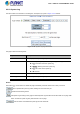
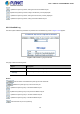
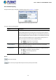

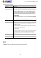
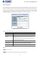
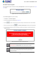
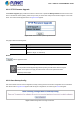
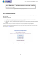
Table Of Contents
- 1. INTRODUCTION
- 2. INSTALLATION
- 3. SWITCH MANAGEMENT
- 4. WEB CONFIGURATION
- 4.1 Main Web Page
- 4.2 System
- 4.2.1 System Information
- 4.2.2 IP Configuration
- 4.2.3 IP Status
- 4.2.4 Users Configuration
- 4.2.5 Privilege Levels
- 4.2.6 NTP Configuration
- 4.2.7 Time Configuration
- 4.2.8 UPnP
- 4.2.9 DHCP Relay
- 4.2.10 DHCP Relay Statistics
- 4.2.11 CPU Load
- 4.2.12 System Log
- 4.2.13 Detailed Log
- 4.2.14 Remote Syslog
- 4.2.15 SMTP Configuration
- 4.2.16 Digital Input/Output
- 4.2.17 Faulty Alarm
- 4.2.18 Web Firmware Upgrade
- 4.2.19 TFTP Firmware Upgrade
- 4.2.20 Save Startup Config
- 4.2.21 Configuration Download
- 4.2.22 Configuration Upload
- 4.2.23 Configuration Activate
- 4.2.24 Configuration Delete
- 4.2.25 Image Select
- 4.2.26 Factory Default
- 4.2.27 System Reboot
- 4.3 Simple Network Management Protocol
- 4.4 Port Management
- 4.5 Link Aggregation
- 4.6 VLAN
- 4.7 Spanning Tree Protocol
- 4.8 Multicast
- 4.8.1 IGMP Snooping
- 4.8.2 Profile Table
- 4.8.3 Address Entry
- 4.8.4 IGMP Snooping Configuration
- 4.8.5 IGMP Snooping VLAN Configuration
- 4.8.6 IGMP Group Port Group Filtering
- 4.8.7 IGMP Snooping Status
- 4.8.8 IGMP Group Information
- 4.8.9 IGMPv3 Information
- 4.8.10 MLD Snooping Configuration
- 4.8.11 MLD Snooping VLAN Configuration
- 4.8.12 MLD Snooping Port Group Filtering
- 4.8.13 MLD Snooping Status
- 4.8.14 MLD Group Information
- 4.8.15 MLDv2 Information
- 4.8.16 MVR (Multicaset VLAN Registration)
- 4.8.17 MVR Status
- 4.8.18 MVR Groups Information
- 4.8.19 MVR SFM Information
- 4.9 Quality of Service
- 4.9.1 Understand QOS
- 4.9.2 Port Policing
- 4.9.3 Port Shaping
- 4.9.4 Port Classification
- 4.9.5 Port Scheduler
- 4.9.6 Port Tag Remarking
- 4.9.7 Port DSCP
- 4.9.8 DSCP-Based QoS
- 4.9.9 DSCP Translation
- 4.9.10 DSCP Classification
- 4.9.11 QoS Control List
- 4.9.12 QoS Status
- 4.9.13 Storm Control Configuration
- 4.9.14 WRED
- 4.9.15 QoS Statistics
- 4.9.16 Voice VLAN Configuration
- 4.9.17 Voice VLAN OUI Table
- 4.10 Access Control Lists
- 4.11 Authentication
- 4.12 Security
- 4.12.1 Port Limit Control
- 4.12.2 Access Management
- 4.12.3 Access Management Statistics
- 4.12.4 HTTPs
- 4.12.5 SSH
- 4.12.6 Port Security Status
- 4.12.7 Port Security Detail
- 4.12.8 DHCP Snooping
- 4.12.9 DHCP Snooping Statistics
- 4.12.10 IP Source Guard Configuration
- 4.12.11 IP Source Guard Static Table
- 4.12.12 ARP Inspection
- 4.12.13 ARP Inspection Static Table
- 4.13 MAC Address Table
- 4.14 LLDP
- 4.15 Diagnostics
- 4.16 Loop Protection
- 4.17 RMON
- 4.18 PTP (MGSW-28240F Only)
- 4.19 Ring (For MGSD-10080F and MGSW-28240F)
- 5. SWITCH OPERATION
- 6. TROUBLESHOOTING
- APPENDIX A
- APPENDIX B: GLOSSARY
- EC Declaration of Conformity

User’s Manual of MGSW-MGSD Series
The page includes the following fields:
Object Description
Enable
Checks the Enable checkbox will enable Digital Input / output function.
Unchecks the Enable checkbox will disable Digital input / output function.
Condition
As Digital Input:
Allows user selecting to High to Low or Low to High. This is means a signal
received by system is from High to Low or From Low to High, it will trigger an
action that logs a customize message or issue the message from the switch.
As Digital Output:
Allows user selecting to High to Low or Low to High. This is means that when
the switch has power failed or port failed then system will issue a High
or Low signal to an external device (such as an alarm).
Allow
s user setting a customize message for Digital Input function alarming.
Event Description
Event
As Digital Input:
Allows user to record alarm message to System log, syslog or issues out via
SNMP Trap or SMTP.
As default SNMP Trap and SMTP are disabled, please enable them first if you
want to issue alarm message via them.
As Digital Output:
Allows user to monitor and alarm from port fail, power fail, Digital Input 0 (DI 0)
and Digital Input 1(DI 1) which means if Digital Output has detected these
event then Digitial Output would be triggered according to the setting of
Condition.
Allow
s user to choose which power module want to be monitored.
Power Alarm
Allow
s user to choose which port want to be monitored.
Port Alarm
Buttons
: Click to save changes.
: Click to undo any changes made locally and revert to previously saved values.
76