
User's Manual

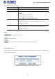

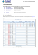
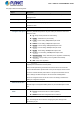
Table Of Contents
- 1. INTRODUCTION
- 2. INSTALLATION
- 3. SWITCH MANAGEMENT
- 4. WEB CONFIGURATION
- 4.1 Main Web Page
- 4.2 System
- 4.2.1 System Information
- 4.2.2 IP Configuration
- 4.2.3 IP Status
- 4.2.4 Users Configuration
- 4.2.5 Privilege Levels
- 4.2.6 NTP Configuration
- 4.2.7 Time Configuration
- 4.2.8 UPnP
- 4.2.9 DHCP Relay
- 4.2.10 DHCP Relay Statistics
- 4.2.11 CPU Load
- 4.2.12 System Log
- 4.2.13 Detailed Log
- 4.2.14 Remote Syslog
- 4.2.15 SMTP Configuration
- 4.2.16 Digital Input/Output
- 4.2.17 Faulty Alarm
- 4.2.18 Web Firmware Upgrade
- 4.2.19 TFTP Firmware Upgrade
- 4.2.20 Save Startup Config
- 4.2.21 Configuration Download
- 4.2.22 Configuration Upload
- 4.2.23 Configuration Activate
- 4.2.24 Configuration Delete
- 4.2.25 Image Select
- 4.2.26 Factory Default
- 4.2.27 System Reboot
- 4.3 Simple Network Management Protocol
- 4.4 Port Management
- 4.5 Link Aggregation
- 4.6 VLAN
- 4.7 Spanning Tree Protocol
- 4.8 Multicast
- 4.8.1 IGMP Snooping
- 4.8.2 Profile Table
- 4.8.3 Address Entry
- 4.8.4 IGMP Snooping Configuration
- 4.8.5 IGMP Snooping VLAN Configuration
- 4.8.6 IGMP Group Port Group Filtering
- 4.8.7 IGMP Snooping Status
- 4.8.8 IGMP Group Information
- 4.8.9 IGMPv3 Information
- 4.8.10 MLD Snooping Configuration
- 4.8.11 MLD Snooping VLAN Configuration
- 4.8.12 MLD Snooping Port Group Filtering
- 4.8.13 MLD Snooping Status
- 4.8.14 MLD Group Information
- 4.8.15 MLDv2 Information
- 4.8.16 MVR (Multicaset VLAN Registration)
- 4.8.17 MVR Status
- 4.8.18 MVR Groups Information
- 4.8.19 MVR SFM Information
- 4.9 Quality of Service
- 4.9.1 Understand QOS
- 4.9.2 Port Policing
- 4.9.3 Port Shaping
- 4.9.4 Port Classification
- 4.9.5 Port Scheduler
- 4.9.6 Port Tag Remarking
- 4.9.7 Port DSCP
- 4.9.8 DSCP-Based QoS
- 4.9.9 DSCP Translation
- 4.9.10 DSCP Classification
- 4.9.11 QoS Control List
- 4.9.12 QoS Status
- 4.9.13 Storm Control Configuration
- 4.9.14 WRED
- 4.9.15 QoS Statistics
- 4.9.16 Voice VLAN Configuration
- 4.9.17 Voice VLAN OUI Table
- 4.10 Access Control Lists
- 4.11 Authentication
- 4.12 Security
- 4.12.1 Port Limit Control
- 4.12.2 Access Management
- 4.12.3 Access Management Statistics
- 4.12.4 HTTPs
- 4.12.5 SSH
- 4.12.6 Port Security Status
- 4.12.7 Port Security Detail
- 4.12.8 DHCP Snooping
- 4.12.9 DHCP Snooping Statistics
- 4.12.10 IP Source Guard Configuration
- 4.12.11 IP Source Guard Static Table
- 4.12.12 ARP Inspection
- 4.12.13 ARP Inspection Static Table
- 4.13 MAC Address Table
- 4.14 LLDP
- 4.15 Diagnostics
- 4.16 Loop Protection
- 4.17 RMON
- 4.18 PTP (MGSW-28240F Only)
- 4.19 Ring (For MGSD-10080F and MGSW-28240F)
- 5. SWITCH OPERATION
- 6. TROUBLESHOOTING
- APPENDIX A
- APPENDIX B: GLOSSARY
- EC Declaration of Conformity

User’s Manual of MGSW-MGSD Series
The page includes the following fields:
Object Description
Th
is is the logical port number for this row,
* means selection all ports of
Managed Switch.
Port
Th
is function provides input per port description and the available letters is 12.
Port Description
The current lin
k state is displayed graphically. Green indicates the link is up and
red that it is down.
Link
Provides the current li
nk speed of the port.
Current Link Speed
Configured Link Speed
Select any available link speed for the given switch port. Draw the menu bar to
select the mode.
All- Setups whole ports with the same setting.
Disable – Shutdowns the port manually.
10 HDX - Forces setting 10Mbps/Half-Duplex mode.
10 FDX - Forces setting 10Mbps/Full-Duplex mode.
100 HDX - Forces setting 100Mbps/Half-Duplex mode.
100 FDX - Forces setting 100Mbps/Full-Duplex mode.
1G FDX - Force setting 1000Mbps/Full-Duplex mode.
10G FDX – Forces setting 10000Mbps/Full-duplex mode.
Auto Fiber (10G) – Setup 10G firber port for negotiation automatically.
Auto Fiber - Setup 1G fiber port for negotiation automatically.
Auto - Setup Auto negotiation.
When Auto Speed is selected on a port, this section indicates the flow control
capability that is advertised to the link partner.
When a fixed-speed setting is selected, that is what is used. The Current Rx
column indicates whether pause frames on the port are obeyed, and the Current
Tx column indicates whether pause frames on the port are transmitted. The Rx
and Tx settings are determined by the result of the last Auto-Negotiation.
Check the conf
igured column to use flow control. This setting is related to the
setting for Configured Link Speed.
Flow Control
Maximum Frame Size
Enter the maximum frame size allowed for the switch port, including FCS. The
allowed range is 1518 bytes to 9600 bytes for TP port and 9000 bytes for Fiber
port.
Excessive Collision
Mode
Configure port transmit collision behavior.
Discard: Discard frame after 16 collisions (default).
Restart: Restart back off algorithm after 16 collisions.
Power Control
The Usage column shows the current percentage of the power consumption per
port. The Configured column allows for changing the power savings mode
parameters per port.
99