
Quick Guide


5
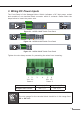
3. Wiring DC Power Inputs
The Front Panel of the Managed Metro Switch indicates a DC inlet power socket
and consists of one terminal block connector within 6 contacts. Please follow the
steps below to insert the power wire.
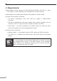
1 3 5 7
2 4 6 8
RingPWR
DC 1
Owner
DC 2
Fault
ACTLNK
ACTLNK
1000
100
RESET
10
9
MGSD-10080F
2
1
4
3
6
5
8
7
10
Console
115200,N,8,1
9
100~240V AC
50/60 Hz
ON
AC POWER
OFF
DC POWER
ON
DC Input Range 36V~60V
OFF
Fault
GNDGNDDO 1DO 0DI 1DI 0
DC 2DC 1
V1+
V2+
Figure 3-1: MGSD-10080F Switch Front Panel
100~240V AC
50/60 Hz
ON
OFF
DC POWER
ON
OFF
Reset
10 12 14 16
9 11 13 15
18 20 22 24
17 19 21 23
2 4 6 8
1 3 5 7
ACT1000 LNK ACT10/100 LNK
Console
115200, N, 8, 1
18 20 22 24
2Fault
DC1
DC2
PWR
4 6 8 10 12 14 16
17 19 21 23
1 3 5 7 9 11 13 15
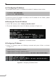
MGSW-24160F
Fault
GNDGNDDO 1DO 0DI 1DI 0
DC 2DC 1
DC Input Range: 36V~60V DC
Please refer to user’s manual before
connect the DC wire.
CAUTION
Figure 3-2: MGSW-24160F Switch Front Panel
100~240V AC
50/60 Hz
ON
AC POWER
OFF
DC POWER
ON
OFF
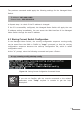
Ring R.O.
FaultFAN2
FAN1
PWR
DC 2
DC 1
DC Input Range:
36V~60V
2 4 6 8 10 12 14 16 18 20 22 24 26 28
272625242322212019181716151413121110987654321 28
Console
Reset
115200, N, 8, 1
Fault
GNDGNDDO 1DO 0DI 1DI 0
DC 2DC 1
1 2 3 4
2 4
MGSW-28240F
Figure 3-3: MGSW-28240F Switch Front Panel
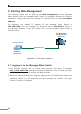
Tighten the wire-clamp screws for preventing the wires from loosening.
1 2 3 4 5 6
V1+ V1- V2+ V2-
Power 1 Power 2
Positive(+)Pin Negative(-)Pin
ManagedMetroSwitch Pin 1 / 5 Pin 2 / 6
Note
The wire gauge for the terminal block should be in the range from
12 to 24AWG.