
User's Manual

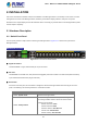

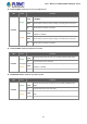

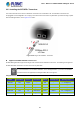
Table Of Contents
- 1. INTRODUCTION
- 2. INSTALLATION
- 3. SWITCH MANAGEMENT
- 4. WEB CONFIGURATION
- 4.1 Main Web Page
- 4.2 System
- 4.2.1 Management
- 4.2.1.1 System Information
- 4.2.1.2 IP Configuration
- 4.2.1.3 IP Status
- 4.2.1.4 Users Configuration
- 4.2.1.5 Privilege Levels
- 4.2.1.6 NTP Configuration
- 4.2.1.7 Time Configuration
- 4.2.1.8 UPnP
- 4.2.1.9 DHCP Relay
- 4.2.1.10 DHCP Relay Statistics
- 4.2.1.11 CPU Load
- 4.2.1.12 System Log
- 4.2.1.13 Detailed Log
- 4.2.1.14 Remote Syslog
- 4.2.1.15 SMTP Configuration
- 4.2.2 Simple Network Management Protocol
- 4.2.3 RMON
- 4.2.4 DHCP server
- 4.2.1 Management
- 4.3 Switching
- 4.3.1 Port Management
- 4.3.2 Link Aggregation
- 4.3.3 VLAN
- 4.3.4 Spanning Tree Protocol
- 4.3.5 Multicast
- 4.3.6 MLD Snooping
- 4.3.7 MVR (Multicast VLAN Registration)
- 4.3.8 LLDP
- 4.3.9 MAC Address Table
- 4.3.10 Loop Protection
- 4.3.11 UDLD
- 4.3.12 GVRP
- 4.4 Quality of Service
- 4.5 Security
- 4.6 Maintenance
- 5. SWITCH OPERATION
- 6. TROUBLESHOOTING
- APPENDIX A: Networking Connection
- APPENDIX B : GLOSSARY

User’s Manual of MGSW-28240F Managed switch
22
2. INSTALLATION
This section describes the hardware features and installation of the Managed Switch on the desktop or rack mount. For easier
management and control of the Managed Switch, familiarize yourself with its display indicators, and ports. Front panel
illustrations in this chapter display the unit LED indicators. Before connecting any network device to the Managed Switch, please
read this chapter completely.
2.1 Hardware Description
2.1.1 Switch Front Panel
The front panel provides a simple interface monitoring the Managed Switch. Figures 2-1-1 show the front panels of the
Managed Switches.
MGSW-28240F Front Panel
Figure 2-1-1: Front Panel of MGSW-28240F
■ Gigabit TP interface
10/100/1000BASE-T copper, RJ45 twisted-pair: Up to 100 meters.
■ SFP slots
100/1000BASE-X mini-GBIC slot, SFP (Small Factor Pluggable) transceiver module: From 550 meters (Multi-mode fiber),
up to 10/30/50/70/120 kilometers (Single-mode fiber).
■ Reset button
On the left of the front panel, the reset button is designed to reboot the Managed Switch without turning off and on the
power. The following is the summary table of the reset button functions:
Reset Button Pressed and Released Function
< 5 sec: System reboot Reboot the Managed Switch
> 5 sec: Factory Default
Reset the Managed Switch to Factory Default configuration.
The Managed Switch will then reboot and load the default
settings as shown below:
。 Default Username: admin
。 Default Password: admin
。 Default IP address: 192.168.0.100
。 Subnet mask: 255.255.255.0
。 Default Gateway: 192.168.0.254