
User's Manual

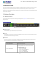

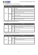

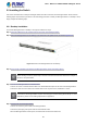
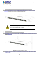
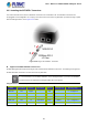
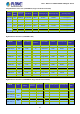
Table Of Contents
- 1. INTRODUCTION
- 2. INSTALLATION
- 3. SWITCH MANAGEMENT
- 4. WEB CONFIGURATION
- 4.1 Main Web Page
- 4.2 System
- 4.2.1 Management
- 4.2.1.1 System Information
- 4.2.1.2 IP Configuration
- 4.2.1.3 IP Status
- 4.2.1.4 Users Configuration
- 4.2.1.5 Privilege Levels
- 4.2.1.6 NTP Configuration
- 4.2.1.7 Time Configuration
- 4.2.1.8 UPnP
- 4.2.1.9 DHCP Relay
- 4.2.1.10 DHCP Relay Statistics
- 4.2.1.11 CPU Load
- 4.2.1.12 System Log
- 4.2.1.13 Detailed Log
- 4.2.1.14 Remote Syslog
- 4.2.1.15 SMTP Configuration
- 4.2.2 Simple Network Management Protocol
- 4.2.3 RMON
- 4.2.4 DHCP server
- 4.2.1 Management
- 4.3 Switching
- 4.3.1 Port Management
- 4.3.2 Link Aggregation
- 4.3.3 VLAN
- 4.3.4 Spanning Tree Protocol
- 4.3.5 Multicast
- 4.3.6 MLD Snooping
- 4.3.7 MVR (Multicast VLAN Registration)
- 4.3.8 LLDP
- 4.3.9 MAC Address Table
- 4.3.10 Loop Protection
- 4.3.11 UDLD
- 4.3.12 GVRP
- 4.4 Quality of Service
- 4.5 Security
- 4.6 Maintenance
- 5. SWITCH OPERATION
- 6. TROUBLESHOOTING
- APPENDIX A: Networking Connection
- APPENDIX B : GLOSSARY

User’s Manual of MGSW-28240F Managed switch
23
2.1.2 LED Indications
The front panel LEDs indicate instant status of power and system status, fan status, port links / PoE-in-use and data activity;
they help monitor and troubleshoot when needed. Figures 2-1-2 show the LED indications of the Managed Switches.
MGSW-28240F Front Panel
Figure 2-11 LED Panel of MGSW-28240F
LED definition
System
LED Color Function
Ring Green
Lights Indicates that Ring state is in idle.
Blinks Indicates that the Ring state is protected.
R.O. Green
Lights Indicates that the switch is set to ring owner.
Off Indicates that the switch doesn’t set to ring owner.
DC1 Green Lights Indicates that the Switch is powered on by DC1 input.
DC2 Green
Lights
Indicates that the Switch is powered on by DC2 input.
FAN1 Green
Lights
Indicates that the FAN1 has stopped.
FAN2 Green
Lights
Indicates that the FAN2 has stopped.
Fault Red
Lights
Indicates that Switch AC/DC or port has failed.
PWR Green
Lights Indicates that the Switch is powered on.
Blinks Indicates the System is running under booting procedure.