8/16/32-Ch Network Video Recorder NVR Series Quick Installation Guide
Table of Contents Chapter 1. Introduction..............................................................................................3 1.1 Before Installation.............................................................................................3 Chapter 2. Physical Description and Installation...........................................................4 2.1 NVR-820 / NVR-1620 8/16-Ch Network Video Recorder......................................4 2.1.1 Package Contents............................
Chapter 1. Introduction Thank you for purchasing PLANET 8/16/32-Ch Network Video Recorder. The Network Video Recorder is designed for use within a surveillance system, and performs recordings and playbacks from network cameras in the system. It is a recording device using a hard disk drive to record camera pictures instead of using video tapes so that pictures recorded by repeated overwriting will not experience deterioration of the recorded picture quality.
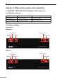
Chapter 2. Physical Description and Installation 2.1 NVR-820 / NVR-1620 8/16-Ch Network Video Recorder 2.1.1 Package Contents 1 x NVR 1 x Power Cord 1 x Power Adapter 1 x CD-ROM 8 x HDD Screw 2 x SATA Cable 2 x HDD Bracket 4 x Bracket Screw 1 set x Feet Pad 1 x Quick Installation Guide 2.1.
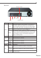
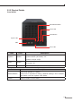
Rear Panel Audio Input / Output HDMI Ethernet VGA Power LED Power Buttons Power Reset Buzzer Beep Microphone Input Status Definitions Green Solid green indicates normal operation. Slow blinking in green after pressing and holding the reset button for 5 seconds indicates the device will enter the restore default process. Other LEDs remain unchanged during this state. Red System off (with power cord still plugged in) Amber Fast blinking in amber indicates the system is initializing/ starting.
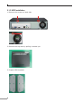
2.1.3 HDD Installation 1. Remove the screws on back side. 2. Remove the top case by pulling it toward you. 3. Prepare HDD brackets.
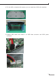
4. Fix the HDD on bracket with screws; you can install two HDDs with brackets. 5. Prepare SATA cable and install it on SATA data connector and SATA power connector.
6. Install SATA cable on the HDD. 7. Fix HDD brackets on system with screws. 2.2 NVR-3210 32-Ch Network Video Recorder 2.2.
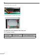
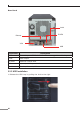
2.2.2 Physical Details Front Panel Reset/Restart Button Power LED Power Button System LED USB Event LED LEDs Color Description System Amber Firmware upgrade: blinking System failure (AP failed): off System normal: solid Event Amber Event recording: solid No event: off Power Blue Power on/Restart/Reset to default/OS failed: solid Button Description Reset/Restart Press and release for restart. Press over 3 seconds to reset to default settings.
Rear Panel Audio E-SATA Ethernet VGA USB Connector Description USB Connect your USB flash disk for firmware upgrade and backup VGA VGA output E-SATA External E-SATA HDD Ethernet 10/100/1000Mbps network Audio Line in / Line out / Mic. 2.2.3 HDD Installation 1. Release the HDD tray by pulling the lock to the right.
2. Pull the HDD tray out of the case. 3. Place the HDD on the bottom of the tray. 4. Put the HDD tray back to the case.
5. Push the tray door back to the case to secure it. 2.3 NVR-3250 32-Ch Rack-mount Network Video Recorder 2.3.1 Package Contents 1 x NVR 1 x Power Cord 1 x RJ45 Cable 1 x CD-ROM 16 x HDD Screw 2 x Angle Bar 4 x Angle Screw 4 x Handle Screw 2 x Handle Kit 1 x Quick Installation Guide 2.3.
LEDs Color Description Power Blue During power on / restart / reset to default / OS failure: solid System Amber During firmware upgrade: blinking System failure (AP failure): Off System normal: Solid Event Amber During event recording: solid No event: Off Rear Panel AC Power Power Supply Fan System Fan VGA Output Gigabit Ethernet USB x 2 Connector Line in / Line out / Mic.
2.3.3 HDD Installation 1. Start by removing the front plate. 2. To remove the front plate, turn the tool-less screws on both sides counter-clockwise to loosen it from the unit. Please note the screws will still be attached to the front plate even after the screws are completely loosened from the unit. 3. Simply pull to remove the front plate once the screws are loosened from the unit.
4. Pull out the HDD tray by the latch. 5. Pull out the HDD tray further to be removed. 6. Once the tray is removed from the unit, note there are four holes, which are used to secure the HDD.
7. Once the HDD is placed in the tray, flip it over and secure the HDD with the screws. 8. Push the tray back into the unit and push it all the way in. 9. Secure the tray by pushing in the latch, which locks the tray with the unit.
2.4 NVR-3280 32-Ch Rack-mount Network Video Recorder with 8-bay Hard Disks 2.4.1 Package Contents 1 x NVR 1 x Power Cord 1 x RJ45 Cable 1 x CD-ROM 32 x HDD Screw 2 x Angle Bar 4 x Angle Screw 4 x Handle Screw 2 x Handle Kit 1 x Quick Installation Guide 2.4.
Button Description Reset/Restart Press and release for restart. Press over 3 seconds to reset to default settings. Don't release the button until the system LED blinks. Power Press to start or shut down. Rear Panel Gigabit Ethernet 1 Line in / Line out / Mic.
2.4.3 HDD Installation 1. Start by removing the front plate. 2. To remove the front plate, turn the tool-less screws on both sides counterclockwise to loosen it from the unit. Please note the screws will still be attached to the front plate even after the screws are completely loosened from the unit. 3. Simply pull to remove the front plate once the screws are loosened from the unit.
4. Pull out the HDD tray by the latch. 5. Pull out the HDD tray further to be removed. 6. Once the tray is removed from the unit, note there are four holes, which are used to secure the HDD.
7. Once the HDD is placed in the tray, flip it over and secure the HDD with the screws. 8. Push the tray back into the unit and push it all the way in. 9. Secure the tray by pushing in the latch, which locks the tray with the unit.
2.5 Web Management Install “Search Device” utility from the CD 1. Please go to Start Programs IVS Search NVR to run the search tool. Then you will see the utility start searching the network. 2. The NVR should be located and its IP address should be displayed: Double-click on it and the program should automatically access the NVR’s web administration page from your default browser.
3. Login the Homepage The Web management allows you to access and manage the Network Video Recorder easily. Launch the Web browser and then enter the IP address. The default IP address is 192.168.0.20. And fill out the User Name and Password to login the Web management. The default User Name and Password are both admin. Further configurations and information can be found in the user’s manual (CD).