IEEE 802.
Trademarks Copyright PLANET Technology Corp. 2006. Contents subject to revision without prior notice. PLANET is a registered trademark of PLANET Technology Corp. All other trademarks belong to their respective owners. Disclaimer PLANET Technology does not warrant that the hardware will work properly in all environments and applications, and makes no warranty and representation, either implied or expressed, with respect to the quality, performance, merchantability, or fitness for a particular purpose.
TABLE OF CONTENTS 1. INTRODUCTION.......................................................................................................................................... 4 1.1 CHECKLIST ................................................................................................................................................ 4 1.2 ABOUT THE POWER OVER ETHERNET INJECTOR .......................................................................................... 4 1.3 FEATURES ............................
1. INTRODUCTION 1.1 Checklist Thank you for purchasing our POE-152 IEEE 802.
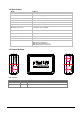
1.4 Specification Model Ethernet Connector POE-152 2 x RJ-45( 1 for data + DC out, 1 for Data in) Ethernet Data rate 10/100/1000Mbps( vary on Ethernet device attached) Input voltage DC 48V, 0.
2. HARDWARE INSTALLATION This product provides three different running speeds – 10Mbps, 100Mbps, 1000Mbps in the same device and automatically distinguishes the speed of incoming connection. This section describes the hardware features of POE-152. Before connecting any network device to the POE-152, read this chapter carefully. 2.1 Before Installation Before your installation, it is recommended to check your network environment. If there is any IEEE 802.
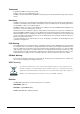
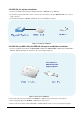
2.2 POE-152, the Injector installation 1. Connect a standard network cable from Switch/workstation to “Ethernet” port of POE-152. 2. Connect the long cable that will be used to connect to the remote device to the port “Ethernet + DC”. The screen in Figure 1 appears. 3. Connect the AC adapter to “DC 48V” of POE-152. The power LED will be steady on. Figure 1: the Injector installation 2.3 POE-152 and POE-152S, the IEEE 802.3af Injector and Splitter installation 1.
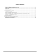
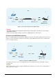
Figure 3: Connection architecture over POE-152/152S Notice: 1. According to IEEE 802.3af standard, the POE-152 will not inject power to the cable if not connecting to IEEE 802.3af devices. 2. Please ensure the output voltage is correct before applying power to remote device. 2.4 Connect with IEEE 802.3af devices Due to the capability of IEEE 802.3af standard, the POE-152 can directly connect with any IEEE 802.3af end-nodes like wireless access point, VoIP phones and Internet camera where support IEEE 802.
3.TROUBLESHOOTING This chapter contains information to help you solve issues. If the POE-152 is not functioning properly, make sure the POE-152 was set up according to instructions in this manual. The PoE LED is not lit Solution: Check the cable connection between POE-152 and IEEE 802.3af device. Why I connect my PoE device to POE-152 and it cannot power on? Solution: 1. Please check the cable type of the connection from POE-152 to the other end.
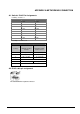
APPENDIX A NETWORKING CONNECTION A.
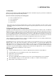
There are 8 wires on a standard UTP/STP cable and each wire is color-coded. The following shows the pin allocation and color of straight cable and crossover cable connection: Figure A-1: Straight-Through and Crossover Cable Please make sure your connected cables are with same pin assignment and color as above picture before deploying the cables into your network.