User’s Manual ICS-100 / ICS-102 / ICS-102S15 RS-232/RS-422/RS-485 over 100Base-FX / 10/100Base-TX Media Converter
User’s Manual of ICS-10x Trademarks Copyright © PLANET Technology Corp. 2008. Contents subject to which revision without prior notice. PLANET is a registered trademark of PLANET Technology Corp. All other trademarks belong to their respective owners.
User’s Manual of ICS-10x TABLE OF CONTENTS 1. INTRODUCTION .............................................................................................................1 1.1 PACKAGE CONTENTS .................................................................................................................................. 1 1.2 HOW TO USE THIS MANUAL ......................................................................................................................... 1 1.3 PRODUCT DESCRIPTION ............
User’s Manual of ICS-10x 4.5 SERIAL PORT CONFIGURATION .................................................................................................................. 47 5. SOFTWARE VCOM UTILITY .......................................................................................49 5.1 INSTALLING THE VCOM UTILITY ................................................................................................................ 49 5.2 SEARCH THE DEVICE.....................................................
User’s Manual of ICS-10x 1. INTRODUCTION Thank you for purchasing PLANET Serial over Fast Ethernet Media Converter – ICS-10x series. Terms of “Serial Media Converter” means the products mentioned titled in the cover page of this User’s manual 1.1 Package Contents Open the box of the Serial Media Converter and carefully unpack it.
User’s Manual of ICS-10x 1.3 Product Description The Web-Smart ICS-10x series Media Converter / Device Server provide to converts Serial RS-232 / RS-422 / RS-485 communication interface over Fast Ethernet networking. There are RJ-45/SC connectors and single-mode/multi-mode media for your needs. Ethernet signal that allows two types of segments to connect easily, efficiently and inexpensively.
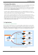
User’s Manual of ICS-10x Process Control To monitor, configure and manage the Robot conveyer including other machines in a manufacturing, PLC (Programmable Logical Control) is required. The PLC is used to drive above the manufacturing machines process. The ICS-10x can be set to TCP Server mode and connect the PLC. The administrator can configure and set command settings through Fast Ethernet intranet to control the PLC, the administrator and workstation.
User’s Manual of ICS-10x Surveillance motion control – Pair Connection Mode Using pair connection along with fiber optical patch cord, the ICS-10x extend RS-232/RS-485 interfaces distance from surveillance and scanner to the control keyboard/joystick which is installed in the remote monitor center. Figure 1-4 Serial Converter for distance extend application 1.
User’s Manual of ICS-10x ¾ Co-work with PLANET MC family Media Chassis ( MC-700/1000R/1500) LED indicators for easy network diagnose Reset Button at the front panel for reset to factory default 1.
User’s Manual of ICS-10x Dimension (W x D x H) 97 x 70 x 26mm Weight 200g Power Supply External Power Adaptor 5V DC / 2A max. Power Consumption 5.5 Watts (maximum) Mechanical Metal Operating Temperature: 0~50 Degree C Environment Storage Temperature: -10~70 Degree C Humidity: 10%~90% RH (operating) 5%~90% RH (Storage) Emissions FCC Class A, CE Certification Class A IEEE 802.3 10Base-T Standards IEEE 802.
User’s Manual of ICS-10x 2. INSTALLATION This section describes the hardware features and installation of the ICS-10X’s components on the desktop or shelf. For easier management and control of the ICS-10x, familiarize yourself with its display indicators, and ports. Front panel illustrations in this chapter display the unit LED indicators. Before connecting any network device to the Serial Media Converter, please read this chapter completely. 2.1 Hardware Description 2.1.
User’s Manual of ICS-10x Figure 2-2 PLANET ICS-100 Front Panel ICS-102 / ICS-102S15 – RS-232 / RS-422 / RS-485 over 10/100Base-FX Figure 2-3 ICS-102 / ICS-102S15 panel layout Figure 2-4 PLANET ICS-102 Front Panel -8-
User’s Manual of ICS-10x 2.1.2 LED Indicators LED Color PWR Green TP or Fiber Serial Green Green Function Lights to indicate that the Converter is powered on. Lights To indicate that the Fast Ethernet Port is successfully connecting to the network at 10Mbps or 100Mbps Blinks To indicate the Fast Ethernet Port is receiving or sending data Lights To indicate that the UART Port is connected successfully Blinks To indicate the UART Port is receiving or sending data 2.1.
User’s Manual of ICS-10x To press and release the RESET button. The ICS-10X will back to the factory default mode. Be sure that you backup the current configuration of ICS-10X; else the entire configuration will be erased when pressing the “RESET” button. • Press and release the RESET button shortly, the device will be rebooted. • Press the RESET button more than 10 seconds, the device will back to the factory default mode; the entire configuration will be erased. 2.
User’s Manual of ICS-10x Figure 2-7 ICS-102 / ICS-102S15 stand alone installation Please refers to APPENDIX-A for detailed wiring information of the ICS-10X. To prevent from optic acceptor malfunction, check the both wires / transmitter before power on the converter. 2.2.2 Chassis Installation and Rack Mounting To install the Media Converter in a 10-inch or 19-inch with standard rack, follow the instructions described below.
User’s Manual of ICS-10x Step 4: After the brackets are attached to the chassis, use suitable screws to securely attach the brackets to the rack, as shown in Figure 2-2. Step 5: Precede with the steps 4 and steps 5 of session 2.2.1 Stand-alone Installation to connect the network cabling and supply power to your converter. You must use the screws supplied with the mounting brackets. Damage caused to the parts by using incorrect screws would invalidate your warranty.
User’s Manual of ICS-10x 3. MANAGEMENT This chapter describes how to manage the ICS-10X. Topics include: - Overview - Management methods - Assigning an IP address to the ICS-10X - Logging on to the ICS-10X 3.1 Overview This chapter gives an overview of converter management. The ICS-10X provides a simply WEB browser interface.
User’s Manual of ICS-10x 3.3 Management Methods The way to manage the ICS-10X: - Web Management via a network or dial-up connection 3.3.1 Web Management The PLANET Web-Smart Media Converter provides a built-in browser interface. You can manage the ICS-10X remotely by having a remote host with web browser, such as Microsoft Internet Explorer, Netscape Navigator or Mozilla Firefox. Using this management method: The ICS-10X must have an Internet Protocol (IP) address accessible for the remote host.
User’s Manual of ICS-10x Figure 3-2 Login screen 1. For security reason, please change and memorize the new password after this first setup. 2. Only accept command in lowercase letter under web interface.
User’s Manual of ICS-10x 4. WEB CONFIGURATION The ICS-10X Web Smart Media Converter provide Web interface for Converter smart function configuration and make the Converter operate more effectively - They can be configured through the Web Browser. A network administrator can manage and monitor the ICS-10x from the local LAN. This section indicates how to configure the Media Converter to enable its smart function. 4.
User’s Manual of ICS-10x 4.2 System 4.2.1 System Information The System Information page provides information for the current device. System Info page helps a network manager to identify the versions and IP Address etc. The screen in Figure 4-2 appears. Figure 4-2 System Information screen The page includes the following fields: • Model Name Specifies the device Model Name. • Software Version The current software version running on the device. • MAC Address Specifies the device MAC address.
User’s Manual of ICS-10x 4.2.2 Password Setting This function provides administrator to secure Web login. The screen in Figure 4-3 appears. Figure 4-3 Password Setting screen The page includes the following configurable data: Login Name Displays the user name. New Password Specifies the new password. The password is not displayed. As it entered an “y” corresponding to each character is displayed in the field. (The maximum length is 15 characters) Confirm Password This confirms the new password.
User’s Manual of ICS-10x 4.2.3 Firmware upgrade The Firmware Upgrade page contains fields for downloading system image files from the Local File browser to the device. The screen in Figure 4-4 appears. Figure 4-4 Firmware Upgrade screen To open Firmware Upgrade screen perform the folling: 2. Click System -> Firmware Upgrade then click Load. 3. The Firmware Upgrade screen is displayed as in Figure 4-5.
User’s Manual of ICS-10x 4. Then the “Firmware Upgrade Mode” displayed as in Figure 4-6. Figure 4-6 Firmware Upgrade screen Click the “Browse” button of the main page, the system would pop up the file selection menu to choose firmware. Figure 4-7 Windows file selection menu popup 5. Select on the firmware then click “Upgrade”. The firmware upgrade may take 60 seconds. Do not power off the converter until the update progress is complete.
User’s Manual of ICS-10x 4.2.4 Factory Default The Factory Default can reset the ICS-10x back to the factory default mode. Be aware that the entire configuration will be reset, and the IP address of the ICS-10x will be set to “192.168.0.100”. The screen in Figure 4-8 appears. Figure 4-8 Factory Default progress screen 4.2.5 System Reboot The System Reboot can restart the ICS-10x. The screen in Figure 4-9 appears.
User’s Manual of ICS-10x 4.3 Network Configuration This function allows setting the value for network configuration. The value is DHCP client, IP address, Subnet Mask, Gateway, DNS and system name. Press the “Apply” button to set the value. The screen in Figure 4-10 appears. Figure 4-10 Network Configuration screen The page includes the following configurable data: • DHCP Client Disable or enable the DHCP function.
User’s Manual of ICS-10x When DHCP Client is set to Enable, the IP Address, Subnet Mask, Gateway and DNS fields are not allow to be changed. If the Media Converter is set to DHCP Client enable, you can use PLANET Smart Discovery or PLANET VCOM Utility to search the Media Converter which with DHCP assigned IP address. 4.4 Operation Mode The ICS-10x make connected Serial equipment becomes IP-based. That also makes them be able to connect to a TCP/IP networking immediately.
User’s Manual of ICS-10x Other ICS-10x with TCP Client mode It opens the TCP port of ICS-10x to wait for serial application to establish a TCP connection. After the connection is established, data can be transmitted in both directions. The parameter defines the maintenance status for listen for the TCP connection. Figure 4-12 TCP Server mode The screen in Figure 4-13 appears. When the changed operation mode, the user should be changed the Serial Port Configuration.
User’s Manual of ICS-10x • Inactive Timeout Example: Use the parameter to set an inactive timeout. The unit drops the connection if there is no activity on the serial line before the set time expires. To disable the inactive timeout enter “0”.
User’s Manual of ICS-10x Figure 4-15 Example: Serial Port Configuration screen Hyper Terminal setup a new connection with TCP/IP Winsock 3.
User’s Manual of ICS-10x 4. On the File menu, click New Connection. 5. In the Name box, type a name that describes the connection. 6. In the Icon box, click the appropriate icon, and then click OK. Figure 4-17 Example: Hyper Terminal – Create new connection 7. In the Connect To dialog box, choose which port or modem you want to use in the Connect using drop-down box. Figure 4-18 Example: Hyper Terminal – Connect type 8.
User’s Manual of ICS-10x Figure 4-19 Example: Hyper Terminal configuration Value Description Host address The address or name of the connection you want to create. This can be in standard Internet dotted notation (for example, w.x.y.z) or can be the site's user-friendly name. port 10. The number of the port that you want the connection to use. Port 23 is the default. Then can use the console like connect the serial cable with the switch.
User’s Manual of ICS-10x 4.4.
User’s Manual of ICS-10x 4.4.3 UDP Client mode When the ICS-10x be configured to UDP Client mode, it allows Serial device that connected to serial port of ICS-10x to quickly transmit data to multiple Remote Hosts over Intranet or Internet network by unicast or multicast. It also makes the Serial device to receive data from more than one Remote Hosts. The parameter defines the maintenance status for listen for the UDP connection.
User’s Manual of ICS-10x The page includes the following fields: • Local UDP Port Enter the local port number • Remote Address Enter the IP address of the remote device. • Remote Port Enter the remote port number of the remote device. 4.4.4 Virtual COM mode When the ICS-10x be configured to Virtual COM mode, it allows Serial device that connected to serial port of ICS-10x to establish TCP communication over Intranet or Internet network between Remote Host (Computer).
User’s Manual of ICS-10x The page includes the following fields: • TCP Port Number The TCP port that ICS-10X uses to listen to connections and that other device must use to contact ICS-10X. To avoid conflicts with well known TCP ports, the default is set to “1024”. • Inactive Timeout Use the parameter to set an inactive timeout. The unit drops the connection if there is no activity on the serial line before the set time expires. To disable the inactive timeout enter “0”.
User’s Manual of ICS-10x Figure 4-28 Example: Virtual COM Configuration screen 2.
User’s Manual of ICS-10x VCOM Utility to create virtual COM port 3. This mode will run with the software-“PLANET VCOM Utility”. Open the VCOM utility, click “Search Device” to point out the ICS-10x that want to be configured. Figure 4-30 Example: Virtual COM Configuration screen 4.
User’s Manual of ICS-10x Hyper Terminal setup a new connection with virtual COM port 5. On the File menu, click New Connection. 6. In the Name box, type a name that describes the connection. 7. In the Icon box, click the appropriate icon, and then click OK. Figure 4-32 Example: HyperTerminal Configuration screen 8. In the Connect to dialog box, choose which port you want to use in the Connect using drop-down box.
User’s Manual of ICS-10x Figure 4-34 Example: HyperTerminal Com port properties screen 10. After the Virtual COM connection is established, open the VCOM utility again to check the COM9 information. Figure 4-35 Example: VCOM Utility, COM9 information 11. Then can use the console like connect the serial cable with the switch.
User’s Manual of ICS-10x Figure 4-36 Example: Hyper Terminal COM port screen 4.4.5 Telnet Server mode TELNET (TELecommunication NETwork) is a network protocol used on the Internet or local area network (LAN) connections. The Telnet protocol type is the correct setting for most servers and serial devices, such as Managed Ethernet switches or Gateways. In most of the case, the telnet use TCP port 23 as communication port. The parameter defines the maintenance status for Telnet server.
User’s Manual of ICS-10x Figure 4-38 Telnet Server Configuration screen The page includes the following fields: • TCP Port Number The TCP port that ICS-10X uses to listen to connections and that other device must use to contact ICS-10X. To avoid conflicts with well known TCP ports, the default is set to “1024”. • Inactive Timeout Use the parameter to set an inactive timeout. The unit drops the connection if there is no activity on the serial line before the set time expires.
User’s Manual of ICS-10x Setup Operation Mode and Serial Port of ICS-10x 1. Set the ICS-10X mode to “Telnet server mode” from web interface. 2. Set the Serial Port Configuration of ICS-10x as below: Mode: RS-232 Baudrare: 9600 Character Bits: 8 Parity Type : none Stop Bit : 1 Hardware Flow Control: none Execute “Telnet” command from Windows Start Menu 3. Click the Start Menu and go to Run 4. Type "telnet" without the quotes, and hit enter. Figure 4-40 Example Windows Excuse - Telnet 5.
User’s Manual of ICS-10x Figure 4-42 Example Windows Excuse - Telnet 7. To quit the Telnet session, press “CTRL+]” and then type “quit” Figure 4-43 Example Windows Excuse - Telnet Example 2: Putty software in Windows Platform PuTTY is a free implementation of Telnet and SSH for Win32 and Unix platforms, along with an xterm terminal emulator. In this case we use Putty to telnet to the ICS-10x-Telnet Server mode for remote console login. 1.
User’s Manual of ICS-10x Figure 4-44 Putty Configuration screen 8. Then can telnet IP address like to telnet switch’s IP.
User’s Manual of ICS-10x 4.4.6 Pair Connection– Local mode The parameter defines the maintenance status for listen for the pair connection. To make a long distance communication between two serial equipment, configure two ICS-10x with Pair Connection mode and setup one as a Master (Local side) and the other as a Slave (Remote side). Pair Connection – Local (Master) – the ICS-10x is locate close to the Host Computer or control device and connect to it via serial interface.
User’s Manual of ICS-10x 4.4.7 Pair Connection – Remote mode The parameter defines the maintenance status for listen for the pair connection. In effect, this converter will be acting as a TCP client. The screen in Figure 4-48 appears. When the changed operation mode, the user should be changed the Serial Port Configuration.
User’s Manual of ICS-10x Example: Two ICS-10x with Pair Connection mode One be configured as Pair Connection – Local (Master) The other one be configured as Pair Connection – Remote (Slave) Via the RS-485 interface, the external scanners, speed dome cameras and PTZ receivers can be controlled by the keyboard which provides upward, downward, leftward, rightward, clockwise and counterclockwise with the joystick.
User’s Manual of ICS-10x 1. Connect the converter with the IP camera for RS-485 interface like PLANET product: “ICA-651”. 2. Connect the converter with the control keyboard for RS-485 interface like PLANET product: “CAM-KB300”. ICS-10x – Master: be configured as Pair-Connection-Local 3. From Web interface, login the ICS-10x with IP address = 192.168.0.
User’s Manual of ICS-10x Figure 4-52 Pair Connection –Remote, operation mode configuration 6. Set the Serial Port mode of ICS-10x-Slave to RS-485. Figure 4-51 Pair Connection – Local, serial port configuration 7. Then the control keyboard cans remote control the IP camera.
User’s Manual of ICS-10x 4.5 Serial Port Configuration The page shows the converter’s serial Port configuration. The screen in Figure 4-52 appears. Figure 4-52 Converter Status page screen The page includes the following fields: • Mode From the drop-down menu, select the serial port mode: RS232 RS-422 RS-485 • Baudrate The unit and attached serial device, such as a modem, must agree on a speed or baud rate to use for the serial connection, Valid baud rates.
User’s Manual of ICS-10x contained in the serial buffer is paced in an Ethernet packet and sent out the Ethernet port. Silent Time: For the defined period of time passed, the serial port stops data transmission and close the connection to remote host. Drop Character: If the incoming data contain character 1 or character 2, the packet will be dropped The default value is “Disable” ■ Logout Press this function; the web interface will go back to login screen.
User’s Manual of ICS-10x 5. SOFTWARE VCOM UTILITY The ICS-10X Web Smart Media Converter provides software for Converter smart function configuration when the Converter operation mode on “Virtual COM”. - They can be configured through the Console. Two function groups are provide to easy used, can search device and create virtual COM to view as the console port. This program can search ICS-10x Series devices, it will show information of the device.
User’s Manual of ICS-10x 3. The Installing window reports the progress of the installation. 4. Click Finish to complete Figure 5-3 VCOM installation screen 5. To run the PLANET VCOM utility on the computer, click “Start” \ “Programs” \ “PLANET VOM Utility” \ “VCOM” Figure 5-4 VCOM program path The VCOM contains two pages: Search Device and VCOM. The Search Device has device information and the VCOM show the virtual COM information.
User’s Manual of ICS-10x 5.2 Search the Device Click the Search Device button to find the ICS-10X. It will show the ICS-10X device name, project name, MAC address, IP address, Sub Mask, Gateway and the connect port number. 1. Click the shortcut of VCOM on the desktop to run the VCOM program. 2. Click "Search Device" button in Search Device tab. If any ICS-10x series device on the LAN, it will show the device name in the tree report.
User’s Manual of ICS-10x Figure 5-6 VCOM Configuration 5. Then set the HyperTerminal parameter Figure 5-7 Hyper Terminal Configuration 6.
User’s Manual of ICS-10x Figure 5-8 VCOM Configuration 7. Once the Virtual COM Port- COM9 connection is established, from the Windows Device Manager, a COM Port is added to the device list. Figure 5-9 Windows Device Server - Virtual COM Port When the Virtual COM create com port, the Device Manager will add “Virtual Serial Port”. And delete the Port on the VCOM, the device will disappear.
User’s Manual of ICS-10x APPENDIX A A.1 PLANET Smart Discovery Utility For easily list the ICS-10X in your Ethernet environment, the Planet Smart Discovery Utility from user’s manual CD-ROM is an ideal solution. The following install instructions guiding you for run the Planet Smart Discovery Utility. 1. Deposit the Planet Smart Discovery Utility in administrator PC. 2. Run this utility and the following screen appears.
User’s Manual of ICS-10x 1. This utility show all necessary information from the devices, such as MAC Address, Device Name, firmware version, Device IP Subnet address, also can assign new password, IP Subnet address and description for the devices. 2. After setup completed, press “Update Device”, “Update Multi” or “Update All” button to take affect. The meaning of the 3 buttons above are shown as below: Update Device: use current setting on one single device.
User’s Manual of ICS-10x A.4 RJ-45 cable pin assignment 6 32 1 6 321 6 3 21 There are 8 wires on a standard UTP/STP cable and each wire is color-coded.
User’s Manual of ICS-10x A.5 Fiber Optical Cable Connection Parameter The wiring details are as below: ■ Fiber Optical patch Cables: (For ICS-102 / ICS-102S) Standard Fiber Type Cable Specification 100Base-FX Multi-mode 50/125μm or 62.5/125μm 100Base-FX Multi-mode 50/125μm or 62.5/125μm (1310nm) Single-mode 9/125μm (1300nm) A.6 Power Information The power jack of ICS-10X is with 2.5mm in the central post and required +5VDC power input.
EC Declaration of Conformity For the following equipment: RS-232 / RS-422 / RS-485 over 10/100Base-TX Media Converter (1 DB9, 1 RJ-45) *Model Number : ICS-100 *Type of Product : * Produced by: Manufacturer‘s Name : Manufacturer‘s Address : Planet Technology Corp. 11F, No. 96, Min Chuan Road, Hsin Tien Taipei, Taiwan , R. O.C.
EC Declaration of Conformity For the following equipment: RS-232 / RS-422 / RS-485 over 100Base-FX Media Converter (1 DB9, 1 Fiber SC connector) *Model Number : ICS-102 / ICS-102S15 / ICS-105A *Type of Product : * Produced by: Manufacturer‘s Name : Manufacturer‘s Address : Planet Technology Corp. 11F, No. 96, Min Chuan Road, Hsin Tien Taipei, Taiwan , R. O.C.