VDSL2 Router VC-200M / VC-200S User’s Manual
Copyright Copyright© 2008 by PLANET Technology Corp. All rights reserved. No part of this publication may be reproduced, transmitted, transcribed, stored in a retrieval system, or translated into any language or computer language, in any form or by any means, electronic, mechanical, magnetic, optical, chemical, manual or otherwise, without the prior written permission of PLANET.
FCC Caution: To assure continued compliance (example-use only shielded interface cables when connecting to computer or peripheral devices). Any changes or modifications not expressly approved by the party responsible for compliance could void the user’s authority to operate the equipment. This device complies with Part 15 of the FCC Rules.
Revision User’s Manual for VDSL2 Router Model: VC-200M / VC-200S Rev: 2.0 (March 2008) Part No.
Table of Contents CHAPTER 1 INTRODUCTION ................................................................................7 1.1 Feature...............................................................................................................7 1.2 Package Contents ..............................................................................................8 1.3 Physical Details .................................................................................................
3.5.5.1 LAN Setting .................................................................................37 3.5.5.2 DHCP Client List.........................................................................38 3.5.6 NAT .......................................................................................................38 3.5.6.1 Virtual Server...............................................................................39 3.5.6.2 Port Mapping ...................................................................
Chapter 1 Introduction The PLANET VDSL2 Router, VC-200M / VC-200S is based on two core networking technologies: Ethernet and VDSL2 (Very High Speed Digital Subscriber Line 2). This technology offers the absolute fastest possible data transmission speeds over existing copper telephone lines without the need for rewiring. The ideal situation, the date rate of VDSL2 can up to 40Mbps upstream and 100Mbps downstream. The VC-200M / VC-200S supports ITU-T G993.
Selectable VDSL2 transmission modes. User can choose transmission modes (8a,8b,12a,12b,and 17a) through management interface on VC-200M / VC-200S User Friendly Interface. VC-200M / VC-200S can be managed and controlled through Web UI. LAN Features 4-Port Switch. The VC-200M / VC-200S incorporates a 4-port 10/100BaseT switching hub, making it easy to create or extend your LAN. DHCP Server Support.
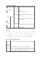
Front Panel LED definition LED State ON When the router is powered on, and in ready state. OFF When the router is powered off. PWR Flashing Router is trying to establish a connection between VC-200M and VC-200S, or telecom’s network. ON Successfully connected between VC-200M and VC-200S, or router and telecom's network, and in ready state. LNK DSL ACT LNK/ACT LAN 1-4 100 Description Flashing Data is being transmitted or received.
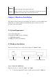
PHONE The RJ-11 connector allows voice communication between the router and phone through a twisted-pair phone wire. VDSL2 The RJ-11 connector allows data communication between the router and the VDSL2 network through a twisted-pair phone wire Chapter 2 Hardware Installation This chapter offers information about installing your router. If you are not familiar with the hardware or software parameters presented here, please consult your service provider for the values needed. 2.1 System Requirement 1.
II. VC-200S. Uses the supplied RJ-11cable connects to VC-200M or VC-200S with your phone company. Step 2. Connect a Workstation to the Router's LAN port Uses the supplied RJ-45 cable connects to PC with the Switching Hub port of VC-200M / VC-200S. Both 10Base-T and 100Base-TX connections can be used simultaneously. If required, using a standard RJ-45 cable connect to any LAN port of VC-200M / VC-200S with a normal Hub.
3. In the Local Area Connection Status window, click Properties. 4. Select Internet Protocol (TCP/IP) and click Properties.
5. Select the Obtain an IP address automatically and the Obtain DNS server address automatically radio buttons. 6. Click OK to finish the configuration. Configuring PC in Windows 2000 1. Go to Start / Settings / Control Panel. In the Control Panel, double-click on Network and Dial-up Connections. 2. Double-click Local Area Connection. 3. In the Local Area Connection Status window click Properties.
4. Select Internet Protocol (TCP/IP) and click Properties. 5. Select the Obtain an IP address automatically and the Obtain DNS server address automatically radio buttons. 6. Click OK to finish the configuration. Configuring PC in Windows 98/Me 1. Go to Start / Settings / Control Panel. In the Control Panel, double-click on Network and choose the Configuration tab. 2. Select TCP/IP -> NE2000 Compatible, or the name of your Network Interface Card (NIC) in your PC.
3. Select the Obtain an IP address automatically radio button. 4. Then select the DNS Configuration tab. 5. Select the Disable DNS radio button and click OK to finish the configuration. Configuring PC in Windows NT4.0 1. Go to Start / Settings / Control Panel. In the Control Panel, double-click on Network and choose the Protocols tab. 2. Select TCP/IP Protocol and click Properties.
3. Select the Obtain an IP address from a DHCP server radio button and click OK. Note: By factory default: DHCP is disabled, Device Mode is Bridge Mode, VC-200M’s default LAN IP address is 192.168.1.100, and VC-200S is 192.168.1.200. So please set fix IP address in TCP/IP properties of your network card (show as below), then you can start your Web Browser to login VC-200M or VC-200S (please see Chapter 3.3).
Chapter 3 Configuration 3.1 Determine your connection settings Before you configure the router, you need to know the connection information supplied by your VDSL2 service provider. 3.2 Connecting the VDSL2 Router to your network Unlike a simple hub or switch, the setup of the VDSL2 Router consists of more than simply plugging everything together.
3.3 Configuring with Web Browser It is advisable to change the administrator password to safeguard the security of your network. 1. To configure the router, open your browser, type http://192.168.1.100 for VC-200M and http://192.168.1.200 for VC-200S in the browsers address box. Save this address in your Favorites for future reference. At login prompt will appear, and default password is “admin”, then click 'LOGIN'. 3.
Step1- Click “Bridge Mode” in VC-200M and VC-200S, and then press “APPLY” to submit setting. Step2- Select profile in VC-200M and VC-200S, we suggest select same profile in VC-200M and VC-200S, otherwise the connection won’t synchronously.
Step3- Click “Active” to make the connection is ready. Step4- After successful connect between VC-200M and VC-200S, the information will show on channel status.
Router Mode Step1- Click “Router Mode” in VC-200M and VC-200S, and then press “APPLY” to submit setting.
Step2- Change LAN IP address, e.g. VC-200M is 192.168.1.100, VC-200S is 192.168.99.100. Step3- Select WAN IP address, e.g. we set WAN to the Static IP address.
Step4- Fill in WAN IP address, e.g.VC-200M is set 10.1.1.100, VC-200S is 10.1.1.200, and gateway address should point each other. Step5- Select profile in VC-200M and VC-200S, we suggest select same profile in VC-200M and VC-200S, otherwise the connection won’t synchronously. Step6- Click “Active” to make the connection is ready.
Step7- After successful connect between VC-200M and VC-200S, the information will show on channel status. Note: Please reference the throughput test for Bridge Mode and Router Mode in Appendix A: Throughput Test for VDSL2 profiles. 3.5 Configuration Menu for Administrator The chapter is only for Administrator. The Homepage is the first screen displayed when a user logs on the VC-200M/VC-200S Web UI. The VC-200M/VC-200S Web UI is categorized into two modules. 1.
2. Advanced Setup- Advanced setup features allow the user to configure all the functions that are supported by VC-200M/VC-200S like routing, and UPnP. 3.5.1 Setup Wizard The Setup Wizard is designed for ease-of-use in order to quickly configure the most common settings. The Admin can view the Setup Wizard link in the Web UI. The wizard’s first step that allows the admin to configure the system host settings displayed show as below. There are five steps to complete the wizard.
3.5.3 System The System link can be viewed in the left navigation bar. The following are the options available under system, show as below. z Host Name Config z System Time z Administrator Settings z Firmware Upgrade z Device Mode z System Status z System Log z Reset 3.5.3.1 Host Name Config To configure System settings, the user has to enter host and domain name. Click on the Host Name Config link in the left navigation bar, show as below.
The screen contains the following details: Filed Description Host Name Enter the host name of the VC-200M/VC-200S. Domain Name Enter the domain name of the VC-200M/VC-200S. 3.5.3.2 System Time To configure the system time zone, click on the System Time link in the left navigation bar, show as below. The screen contains the following details: z Filed Description Set Time Zone Synchronize the system clock with the SNTP server. Click “CANCEL” to exit from this page without saving the changes.
z Click “APPLY” to save the information that has been entered. 3.5.3.3 Administrator Settings To add a user or change user’s password, click on the Administrator Settings link in the left navigation bar, show as below. While adding a user, each user must be assigned a separate port. Hence the number of user that can bee added to the system depends on the number of ports available on the VC-200M/VC-200S. Filed Description Current Password This is the password associate with the administrator.
Note: By factory default: Device Mode is Bridge Mode. 3.5.3.5 Firmware Upgrade To update the system firmware, click on the Firmware Upgrade link in the left navigation bar, show as below. z Click “Browse” to select a specified file name to change the file Name. z Click “APPLY” to start the firmware update. 3.5.3.6 System Status To view system status, click on the System Status link in the left navigation bar, show as below. This screen displays the status of certain important system parameters.
z Click “Release” to release IP Address for the WAN interface. z Click “Renew” to renew the IP Address for the WAN interface. 3.5.3.7 System Logs To view the system logs, click on the System Logs link in the left navigation bar, show as below.
The screen contains the following details: Filed Description Log File This lists all the system events. z Click “Download” to download the log file to the computer. z Click “Clear” to clear this page. z Click “Refresh” to retrieve system event and update the log file. 3.5.3.8 Reset To restart the system, click on the Reset link in the left navigation bar, show as below. z Click “Reset” to restart the system.
3.5.4 WAN The WAN settings can be viewed in the left navigation bar. The following are the options available under WAN, show as below. z Dynamic IP z Static IP z PPPoE z DNS 3.5.4.1 Dynamic IP To configure the WAN interface to dynamically obtain an IP Address, click on the Dynamic IP link in the left navigation bar, show as below.
The screen contains the following details: z Click “APPLY” to save the information that has been entered. z Click “CANCEL” to exit from this page. 3.5.4.2 Static IP To configure the WAN interface to use a Static IP Address, click on the Static IP link in the left navigation bar, show as below.
The Screen contains the following details: Filed Description IP Address assigned by your ISP Enter the IP Address of VC-200M/VC-200S. Subnet Mask Enter the Subnet Mask of VC-200M/VC-200S. ISP Gateway Address Enter the Gateway address of VC-200M/VC-200S. Does ISP provide more IP Address Provides more IP Addresses of the WAN interface. Select the check box to enable this option. 3.5.4.
MTU Enter the maximum connection units of the PPPoE. The MTU range is 1400 to 1492 bytes, by factory default is 1492. Maximum Idle Time This is the period of time required to keep the connection alive if no packets are transmitted.
The screen contains the following details: Filed Description Domain Name Server(DNS) Address Enter the DNS address of the primary DNS server. Secondary DNS Address(optional) Enter the address of the secondary DNS server, if available. z Click “CANCEL” to exit from this page without saving the changes. z Click “APPLY” to save the information that has been entered. 3.5.5 LAN The LAN setting can be viewed in the left navigation bar. The following are the options available under LAN, show as below.
3.5.5.1 LAN Setting To configure the LAN interface, click on the LAN Setting link in the left navigation bar, show as below. The Dynamic Host Configuration Protocol (DHCP) Server gives out IP addresses when a device is booting up and request an IP to be logged on to the network. It must be set as a DHCP client to obtain the IP address automatically. Note: By factory default, the DHCP is disabled, VC-200M’s default LAN IP address is 192.168.1.100, and VC-200S is 192.168.1.200.
IP Pool Ending Address Enter the ending IP Address of the DHCP server. (When Enable DHCP Server) Lease Time Select the lease time of the DHCP server. (When Enable DHCP Server) Local Domain Name Enter the Domain Name of the DHCP server. (When Enable DHCP Server) z Click “CANCEL” to exit from this page without saving the changes. z Click “APPLY” to save the information that has been entered. 3.5.5.
The NAT Settings can be viewed in the left navigation bar. The following are the options available under NAT, show as below. z Virtual Server z Port Mapping z DMZ 3.5.6.1 Virtual Server You can configure the Router as a virtual sever so that remote users can access services such as the Web or FTP server at your local site via public IP address. These addresses can be automatically redirected to local servers configured with private IP addresses.
The screen contains the following details: Filed Description Private IP Enter a private IP Address of specified entry. Private Port Enter a private Port number of the specified entry. Type Select virtual server protocol type of the specified entry. Public Port Enter a public Port number of the internet user to access the virtual server. Enabled Enable the specified entry of the virtual server. z Click “CANCEL” to exit from this page without saving the changes.
The screen contains the following details: Filed Description Server IP Enter the IP Address of a specified local machine. Mapping Port Assign a range of port or specific port number to route the packets. e.g. 8080-8081,21 Enabled Enable a specified entry of the Port Mapping. z Click “CANCEL” to exit from this page without saving the changes. z Click “APPLY” to save the information that has been entered. 3.5.6.
The screen contains the following details: Filed Description Enable Enable or disable the DMZ setting of VC-200M/VC-200S.Select the check box to enable this option. IP Address Enter IP Address of the DMZ host. z Click “CANCEL” to exit from this page without saving the changes. z Click “APPLY” to save the information that has been entered. 3.5.7 Route The Route Settings can be viewed in the left navigation bar. The following are the options available under Route, show as below.
3.5.7.1 Static Route The static routing function determines the path that data follows over your network before and after it passes through your router. You can use static routing to allow different domain users to access the Internet through this Router. To setup Static Routing, click on the Static Routing link in the left navigation bar, show as below. The screen contains the following details: Filed Description Interface Select the direction of WAN or LAN.
PC2 can go to Internet through VC-200M/VC-200S, so please reference as below to fill in static routing table. Interface: LAN Destination IP: 203.67.31.0 Subnet mask: 255.255.255.0 Gateway: 192.168.1.3 3.5.7.2 Routing Table List To view the Routing entry table list of VC-200M/VC-200S, click on the Routing Table by link in the left navigation bar, show as below. z Click “Refresh” to update currently routing list of VC-200M/VC-200S.
3.5.8 UPnP UPnP (Universal Plug and Play) is a distributed, open networking standard that uses TCP/IP for simple peer-to-peer network connectivity between devices. An UPnP device can dynamically join a network, obtain an IP address, convey its capabilities and learn about other devices on the network. In turn, a device can leave a network smoothly an automatically when it is no longer in use. UPnP broadcasts are only allowed on the LAN.
The screen contains the following details: Filed Description Enable UPnP To enable or disable UPnP Setting. Select the check box to Enable or Disable the UPnP function of VC-200M/VC-200S. z Click “CANCEL” to exit from this page without saving the changes. z Click “APPLY” at any time during configure to save the information that you have been entered. Chapter 4 Operating the VDSL2 System 4.1 Configuration Settings Configure and start the VC-200M and the CPE.
4.1.1 Channel Configuration To set direction, Min Data Rate, Max Date Rate, and Max Interleve Delay of channl1, click on the ChannelConfig in the left navigation bar, show as below. The screen contains the following details: Setting Description Direction To which direction shall the settings apply? z Upstream z Downstream Min Date Rate Minimum Payload Date Rate, by factory default is 64 kbps. Max Date Rate Maximum Payload Date Rate, by factory default is 15000 kbps.
4.1.2 Line Configuration Signal-to-Noise Ratio, often written S/N or SNR, is a measure of signal strength relative to background noise. The ratio is usually measured in decibels (dB). If the incoming signal strength in microvolts is Vs, and the noise level, also in microvolts, is Vn, then the signal-to-noise ratio, S/N, in decibels is given by the formula S/N = 20 log10 (Vs/Vn) If Vs = Vn, then S/N = 0. In this situation, the signal borders on unreadable, because the noise level severely competes with it.
The screen contains the following details: Setting Description Direction Select the target direction of downstream or upstream. Target SNRM Set the required SNR Margin×10(50=5dB), by default is 6dB. z Click “CANCEL” to exit from this page without saving the changes. z Click “APPLY” at any time during configure to save the information that you have been entered. 4.1.
frequency bands. Table 1 list 8a, 8b, 21a, 12b, and 17a standard VDSL2 profile about the bandwidth, tones, tone spacing, and line power.
To select VDSL2 profile, click on the ProfileConfig link in the left navigation bar, show as below. The screen contains the following details: Setting Description Profile Select the ten standard VDSL2 profiles. z Click “CANCEL” to exit from this page without saving the changes.Note: By factory default is VDSL2 Profile 17a-Bandplan ITU AnnexB_B12. 4.1.4 Active To enable or disable VDSl2, click on the Active link in the left navigation bar, show as below. The screen contains the following details: Setting Description Line Activate or deactivate the line. z Click “CANCEL” to exit from this page without saving the changes. z Click “APPLY” at any time during configure to save the information that you have been entered. 4.1.
4.1.6 Version Information To view the version information is about Web UI, API Library, Chipset FW, Chipset HW, and DSL Driver.
Appendix A Field Throughput for VDSL2 profiles Router Mode Band Profile Distance 400 Meter (1312 feet) 1000 Meter (3281 feet) 8a, 8b 12a, 12b 17a 20 / 5 15 / 15 15 / 15 20 / 5 20 / 5 20 / 5 (Downstream/Upstream, Unit: Mbps) Bridge Mode Band Profile Distance 400 Meter (1312 feet) 1000 Meter (3281 feet) 8a, 8b 12a , 12b 17a 50 / 10 50 / 30 100 / 30 30 / 10 30 / 10 30 / 10 (Downstream/Upstream, Unit: Mbps) The actual data rate will vary on the quality of the telephone line and environmen
Appendix B Glossary DHCP DHCP stands for Dynamic Host Configuration Protocol. This protocol automatically configures the TCP/IP settings of every computer on your home network. DNS Server Address DNS stands for Domain Name System, which allows Internet host computers to have a domain name (such as www.planet.com.tw) and one or more IP addresses (such as 192.34.45.8).
Internet Service Provider. An ISP is a business that provides connectivity to the Internet for individuals and other businesses or organizations. LAN Local Area Network. A LAN is a group of computers and devices connected together in a relatively small area (such as a house or an office). Your home network is considered a LAN. MAC Address MAC stands for Media Access Control. A MAC address is the hardware address of a device connected to a network. NAT Network Address Translation.
TCP/IP Transmission Control Protocol/Internet Protocol. This is the standard protocol for data transmission over the Internet. WAN Specify the WAN connection type required by your Internet Service Provider, then click "Apply" to provide detailed configuration parameters for the selected connection type. Specify one of the first five options to configure a WAN connection through the RJ-45 port.