SIP IP Phone VIP-254T/VIP-254PT User’s manual Version 1.
Copyright Copyright (C) 2008 PLANET Technology Corp. All rights reserved. The products and programs described in this User’s Manual are licensed products of PLANET Technology, This User’s Manual contains proprietary information protected by copyright, and this User’s Manual and all accompanying hardware, software, and documentation are copyrighted.
Revision User’s Manual for PLANET SIP IP Phone: Model: VIP-254T/VIP-254PT Rev: 1.0 (2008, May) Part No. EM-VIP254V1.
TABLE OF CONTENTS Chapter 1 ................................................................................................ 6 Introduction............................................................................................ 6 Overview............................................................................................................................6 Package Content ...............................................................................................................
Codec ID Setting ......................................................................................................33 DTMF Settings .........................................................................................................34 RPort Settings ...........................................................................................................34 Other Settings ...........................................................................................................35 STUN settings ....
Chapter 1 Introduction 1 Overview Meeting the next-generation Internet telephony service demands, PLANET Technology provides feature-rich, toll-quality Internet telephony service solutions. With 802.3af Power over Ethernet (PoE) IP Phone-VIP-254PT. And the VIP-254T is the cost-effective SIP IP Phone; the VIP-254 series are SIP 2.0 (RFC3261) compliant with SIP digest authentication supports.
• Dynamic IP address assignment, and voice communication The IP Phone can act as a PPPoE/DHCP client, automatically obtaining an IP address for Internet access. • Various field applications compliant The IP Phone is capable of handling peer-to-peer and SIP proxy / IP PBX registration, authentication to interact with major IP PBX/SIP gateway/IP Phone in the market.
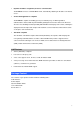
Physical Details The following figure illustrates the front/rear panel of IP Phone. Rear View Rear Panel of VIP-254T/VIP-254PT 1 PC RJ-45 connector, to maintain the existing network structure, connected directly to the PC through straight CAT-5 cable RJ-45 connector, for Internet access, connected directly to Switch/Hub through straight CAT-5 cable. 2 LAN The LAN interface also can be connected with 802.3af PoE switch or converter for power supply (VIP-254PT) 3 DC 5V 4.
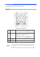
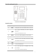
Front View and Keypad function Front Panel of VIP-254T/VIP-254PT Keypad Description 1 LCD Display 2 MENU Menu and all status shall be displayed for users. To bring out the menu selection while IP Phone is in idle state. This is Up ▲ / Down ▼ key and volume setting when 3 ▲ ▼ off-hook off. Show the calls history when on-hook. 4 ENTER 5 CONTACTS 6 FLASH To be used as confirm configuration or enter sub-menu. Enter the phone book selection.
Press to dial the last dialed number when the IP Phone is 10 RD off-hooked. To switch between the usage of the handset and the speaker 11 Handfree devices. 12 Hold To hold the conversation.
Chapter 2 Preparations & Installation 2 Physical Installation Requirement VIP-254T: SIP IP Phone (2 x RJ-45) VIP-254PT: 802.3af PoE SIP IP Phone (2 x RJ-45, 1 x PoE for LAN interface) Step 1: Connecting Handset Handset Step 2: Connecting Power AC Power and Network Plug the Ethernet cable into the back of the base station. Plug the other end of the Ethernet cable into your already prepared network connection.
Power Adapter (5V DC) NOTE: Use only the power adapter shipped with the unit to ensure correct functionality. Step 3: Adjust the stand angle. Press and hole the button of right side to change the stand mount angle. 1 PC RJ-45 connector, to maintain the existing network structure, connected directly to the PC through straight CAT-5 cable RJ-45 connector, for Internet access, connected directly to Switch/Hub through straight CAT-5 cable. 2 LAN The LAN interface also can be connected with 802.
Administration Interface The IP Phone provides GUI (Web based, Graphical User Interface) for machine management and administration. Key pad administration also available for simple configuration. Web configuration access: To start IP Phone web configuration, you must have one of these web browsers installed on computer for management • Microsoft Internet Explorer 6.0.0 or higher with Java support Default IP address of IP Phone is 192.168.0.1. You may now open your web browser, and insert http://192.168.
Chapter 3 Network Service Configurations 3 Configuring and monitoring your IP Phone from web browser The IP Phone integrates a web-based graphical user interface that can cover most configurations and machine status monitoring. Via standard, web browser, you can configure and check machine status from anywhere around the world. Overview on the web interface of IP Phone With web graphical user interface, you may have: More comprehensive setting feels than traditional command line interface.
When users login the web page, users can see the IP Phone system information like firmware version, company…etc in this main page. IP Phone main page LAN IP address configuration via web configuration interface Execute your web browser, and insert the IP address (default: 192.168.0.1) of VIP in the address bar.
LAN mask of IP Phone Subnet Mask Default: 255.255.255.0 Default Gateway Gateway of IP Phone Default: 192.168.0.254 After confirming the modification you’ve done, Please click on the Submit button to apply settings and browse to “Save & Reboot” menu to reboot the machine to make the settings effective. Connection Type Data required. In most circumstances, it is no need to configure the DHCP Fixed IP settings. DHCP client The ISP will assign IP Address, and related information.
Chapter 4 VoIP IP Phone Configurations 4 Phone Book settings IP Phone can set up 140 records of Phone Book. User can make calls via Phone Book feature of IP Phone. Field Phone Book Page Phone Name URL Select Description The default is Page 1. It can select Page1 ~ Page 14 to look round Phone Book records. The record number from 0 ~ 139, it can set up 140 records in total. The name of Phone Book records, it only can input numerals. Fill in the outgoing number (Line Number) or IP address.
If you need to add a phone number into the Phone Book list, you need to input the position, the name, and the phone number (by URL type). When you finished a new phone list, just click the “Add Phone” button. If you want to delete a phone number, you can select the phone number you want to delete then click “Delete Selected” button. If you want to delete all phone numbers, you can click “Delete All” button. For Example: STEP 1: IP Phone had added the above phone numbers.
202 192.168.1.2:5062 STEP 4: Pick up the telephone handset or press Handfree button to dial to this telephone. IP Dialing.. 1 192.168.1.2:5062 Speed Dial settings In Speed Dial setting function you can add/delete Speed Dial number. You can input maximum 10 entries speed dial list. You can setup the Speed Dial number. If you want to use Speed Dial you just dial the speed dial number (from 0~9) and follow the “#” key.
Call Forward This page defines Call Forward function. You can setup the phone number you want to forward in this page. There are three type of Forward mode. You can choose All Forward, Busy Forward, and No Answer Forward by click the icon. All Forward: All incoming call will forward to the number you chosen. You can input the name and the phone number in URL field. If you select this function, then all the incoming call will direct forward to the speed dial number you choose.
Volume Setting This page defines the Handset Volume, Ringer Volume, and the Handset Gain. When you finished the setting, please click the Submit button. Handset Volume is to set the volume for you can hear from the handset.(Handfree mode) Speaker Volume is to set the volume for you can hear from the speaker. Ringer Volume is to set the ringer volume for you can hear. Handset Gain is to set the volume send out to the other side’s handset.
Ringer Setting This page defines the user can set the tinkle of bells when someone ring your IP Phone. If want to set ringer, it need to enable Ringer function and select the Ringer Type you wanted. There are four Ringer Types can be chosen. When you finished the setting, please click the Submit button. Block Setting This page defines the Block Setting to keep the phone slience. You can choose Always Block or Block a period. Always Block: All incoming call will be blocked until disable this feature.
Dial Plan Settings This page defines the Dial Plan Setting function. This function is when you input the phone number by the keypad but you don’t need to press “#”. After time out the system will dial directly. Field Description Drop Prefix The rule of add or replace code. If setup as No, it will add the prefix number prior to the identification number. If setup as Yes, it will replace the identification number. Replace rule The prefix number. It only accept the numeral and the max length is 8.
system will ignore this dial plan. Auto Dial Time Stop dialing after seconds then send dial number out. Use # as send key If setup as Yes, the system sill stop to receive the dialing number when receive the [#] key. The system also will to determine the Auto Dial Time, it will carry out the calling if there isn’t receive the digit after the Auto Dial Time. If setup as No, the system just according to the Auto Dial Time to determine the end time.
Call waiting Settings When you are talking with other people, You can choose If you want to hear the notice when there is a new coming call. If the call waiting function is On, if there is a new incomeing call, you will hear the call waiting notice in your current call. If you set the function to Off, then you will not hear any notice. Hot line Settings This page defines the Hot line setting in this page. When user pick up the handset, the device will call to the specific number automatically.
LAN Settings This page defines the LAN setting in this page. LAN Mode: The default is Bridge mode, and it also provides NAT mode. Bridge: When set as is mode, the LAN and PC ports are in the same network segment. NAT: The LAN and PC ports are in the different network segment, and PC port could enable the DHCP Server function to allot the IP address. IP Type: The default is Fixed IP, and it also provides DHCP Client and PPPoE connection modes. Fixed IP: It could setup the IP address manual.
PC Settings This page defines the PC setting in this page. IP: The IP address of PC port. (In the Bridge mode, the Default IP: 192.168.123.1) Mask: The sub net address. (Default: 255.255.255.0) MAC: The MAC of PC port DHCP Server: It will allot the IP address automatically when enabke this function. Start IP: Start IP of lease table End IP: End IP of lease table.
DDNS Settings This page defines the DDNS setting in this page. You need to have the DDNS account and input the informations properly. You can have a DDNS account with a public IP address then others can call you via the DDNS account. But now most of the VoIP applications are work with a SIP Proxy Server. When you finished the setting, please click the Submit button.
VLAN Settings This page defines the VLAN setting in this page. This function needs to co-operate with network devices which have VLAN function. VLAN Packets: If setup as On, it could receive VLAN messages. VID (802.1Q/TAG): Dispose VLAN ID is add a Tag header after realize enable the VLAN function. The realized voice packets transfer at the same VLAN. The prerequisite is it must the same as VLAN of upper switch. The value range are 2~4094. User Priority (802.1P): To setup the user priority.
Virtual Server This page defines the Virtual Server setting in this page. You could define 24 virtual service information in this page. When you finished the setting, please click the Submit button. Virtual Server Page: There are total page1 to page 3. It could choose the page which want to go over. Num: The serial number. There are total 24 records from Num 0 to 23. Enable: The activate status. The default is Disable, this record will been activate if enable.
PPTP Settings This page defines the PPTP setting in this page. You could setup the PPTP Server connection information. When you finished the setting, please click the Submit button. Service Domain Settings This router comes with the built-in firewall based on the advanced technology of Stateful Packet In Service Domain Function you need to input the account and the related informations in this page, please refer to your ISP provider. You can register three SIP account in the Phon.
LNote: IP Phone can register to three different SIP Proxies at the same time. It can receive any one of different SIP accounts incoming call, and it can switch to any one SIP accounts for making calls through input the switch code. Realm switch code: 1*: Realm 1 2*: Realm 2 3*: Realm 3 For example: The default is realm 1, input the 2* (Follow by the # key) from keypad and hang up the telephone set. It will switch to realm 2, and it can make the SIP calls via realm 2.
Codec Settings This page defines the Codec priority, RTP packet length, and VAD function in this page. You need to follow the ISP suggestion to setup these items. When you finished the setting, please click the Submit button. Codec ID Setting This page defines the Codec ID. Sometimes 2 VoIP device with different Codec ID will cause the interoperability issue. If you are talking with others got some problems, you may ask the other one what kind of Codec ID he use then you can change your Codec ID.
DTMF Settings This page defines the DTMF parameters. Yyou can setup the InBand DTMF, 2833 Out-Band DTMF and Send DTMF SIP Info Enable/Disable in this page. To change this setting, please following your ISP information. When you finished the setting, please click the Submit button. RPort Settings This page defines the RPort Enable/Disable in this page. To change this setting, please following your ISP information. When you finished the setting, please click the Submit button.
Other Settings This page defines the Hold by RFC, Voice/SIP QoS and other settings in this page. To change these settings please following your ISP information. When you finished the setting, please click the Submit button. Hold by RFC: The default is disable, and to start up communication hold back function (RFC definition). Set enable to start up the Hold by RFC function. Voice QoS (Diff-Serv): The Voice QoS feature. SIP QoS (Diff-Serv): The SIP QoS feature.
Auto Configuration This page defines the Auto Configuration (Auto Provision) setting. IP Phone supports TFTP, FTP, HTTP function in total. MAC CIone Setting This page defines the MAC Clone Enable/Disable. This function will copy the MAC address from NIC (Network Interface Card) which placed in PC to LAN port of IP Phone. That because some ISP will limit the MAC address for PPPoE dial-up connection.
Please refer to the following operate procedures for more understandings to carry out the MAC Clone function. 1. Please login IP Phone and browse to “Network -> LAN Settings” page. To switch the LAN mode to NAT mode then press Save&Reboot button to save the settings and reboot machine. 2. Please make sure the network cable of your PC directly connect with PC port of IP Phone, then re-login IP Phone. (In the NAT mode, the default IP address of PC port is http://192.168.123.1 ) 3.
Tone Settings This page defines the Tone settings. This function can setup the related parameters of Dial Tone, Ring Back Tone, Busy Tone, Error Tone and Insert Tone. When you finished the setting, please click the Submit button. Advanced Settings This page defines the advanced functions. When you finished the setting, please click the Submit button. ICMP Not Echo: This function can disable echo when someone ping this device, it can avoid haker try to attack the device.
System Authority In System Authority you can change your login password. Save & Reboot In Save & Reboot you can save the changes you have done. If you want to use new setting in the IP Phone, you have to click the Save button. After you click the Save button, the IP Phone will automatically restart and the new setting will effect.
Firmware Upgrade In Firmware Upgrade function you can update new firmware via HTTP or TFTP methods in this page. You can ugrade the firmware by the following steps: Select the upgrade method and the firmware code type, AP or DSP code. Click the “Browse” button in the right side of the File Location or you can type the correct path and the filename in File Location blank. Select the correct file you want to download to the device then click the Update button.
Field Descriptions Update via There are TFTP/ FTP and HTTP three ways to provide the auto upgrade function. TFTP Server Input the TFTP Server address, and it could input the IP or Domain Name form. TFTP Path Set up the file path. HTTP Server Input the HTTP Server address, and it could input the IP or Domain Name form. HTTP File Path Set up the file path. FTP Server Input the FTP Server address, and it could input the IP or Domain Name form. FTP Username The login username.
new firmware when power on and following the scheduling date and time. - Scheduling only: The machine will only follow the scheduling date and time to check the new firmware. Scheduling (Date) The machine will check the new firmware between the time range by random. Automatic Update There are Notify only and Automatic ways to update. - Notify only: If there are new firmware, the IP Phone will send the “Be Be Be” sounds when pick up the handset to prompt there are new firmware.
Reboot without saving Reboot function you can restart the IP Phone. If you want to restart the IP Phone, you can just click the Reboot button, then the IP Phone will reboot automatically.
Appendix A Voice communications There are several ways to make calls to desired destination in IP Phone. In this section, we’ll lead you step by step to establish your first voice communication via keypad and web browsers operations. Case 1: Voice communication via SIP proxy server _SIP-50 VIP-254T-A Number: 100 Number: 200 VIP-254T-B LAN IP Address LAN IP Address (192.168.0.1) (192.168.0.2) SIP-50 WAN IP Address (192.168.0.
STEP 3: Repeat the same configuration steps on VIP-254T-B, and check the machine registration status, make sure the registrations are completed. STEP 4: To verify the VoIP communication, please pick up the telephone. Dial the destination number to make call between SIP clients. For example, VIP-254T-A (with number 100) with keypad number 200 to VIP-254T-B, or reversely makes calls from SIP client (VIP-254T-B) to the number 100 (VIP-254T-A).
STEP 2: After set up completed and reboot machine, the LCD screen will show below: 10-19 17:20 # Forward # After 2~3 seconds, the LCD screen will show below: 10-19 17:20 AF 2002 Test the scenario: VIP-254T_C pick up the telephone and dial the number 1001(VIP-254T_A), because VIP-254T_A had set up All Forward function to the number 2002(VIP-254T_B), so the number 2002(VIP-254T_B) will ring up then it pick up the telephone and communication with the number 3003(VIP-254T_C).
Machine configuration on the VIP-254T: STEP 1: Please log in VIP-254T_A via web browser, browse to the Phone Settings menu and select the Call Forward config menu. In the setting page, please enable the All Forward function and fill in the Name and URL of VIP-254T_B, and then the sample configuration screen is shown below: STEP 2: After set up completed and reboot machine, the LCD screen will show below: 10-19 17:20 # Forward # After 2~3 seconds, the LCD screen will show below: 10-19 17:20 AF 192.168.0.
Appendix B The method of operation guide In this section, we’ll introduce the features method of operation, and lead you step by step to establish these features. Call Transfer A. Blind Transfer 1. B call to A and they are in the process of conversation. 2. A press “FLASH” button to hold the conversation with B, and input the number of C (Follow by the “#” key). 3. C will ring up, and A hang up the handset. 4. C picks up the handset and conversation with B. B. Attendant Transfer 1.
Switch the Realm (Registration Proxy Server) IP Phone can register to three different SIP Proxies at the same time. It can receive any one of different SIP accounts incoming call, and it can switch to any one SIP accounts for making calls through input the switch code. Realm switch code: 1*: Realm 1 2*: Realm 2 3*: Realm 3 For example: The default is realm 1, input the 2* (Follow by the # key) from keypad and hang up the telephone set. It will switch to realm 2, and it can make the SIP calls via realm 2.
Appendix C VIP-254T / VIP-254PT Specifications Product Model Hardware LAN PC LCD display Speaker Protocols and Standard Standard Voice codec Voice Standard Supplementary services Call history Protocols SIP IP Phone VIP-254T SIP PoE IP Phone VIP-254PT 1 x 10/100Mbps RJ-45 port Power Over Ethernet 802.3af compliant at VIP-254PT 1 x 10/100Mbps RJ-45 port 2 x 16 characters Full duplex hands free speaker phone SIP 2.
EC Declaration of Conformity For the following equipment: *Type of Product *Model Number : SIP IP Phone : VIP-254T * Produced by: Manufacturer‘s Name : Manufacturer‘s Address: Planet Technology Corp. 11F, No 96, Min Chuan Road Hsin Tien, Taipei, Taiwan, R. O.C.
EC Declaration of Conformity For the following equipment: *Type of Product *Model Number : SIP PoE IP Phone : VIP-254PT * Produced by: Manufacturer‘s Name : Manufacturer‘s Address: Planet Technology Corp. 11F, No 96, Min Chuan Road Hsin Tien, Taipei, Taiwan, R. O.C.