H.
Copyright Copyright (C) 2005 PLANET Technology Corp. All rights reserved. The products and programs described in this User’s Manual are licensed products of PLANET Technology, This User’s Manual contains proprietary information protected by copyright, and this User’s Manual and all accompanying hardware, software, and documentation are copyrighted.
Revision User’s Manual for PLANET H.323/SIP VoIP Router: Model: VIP-280 Rev: 1.0 (Sept. 2005) Part No.
TABLE OF CONTENTS Chapter 1 Introduction .......................................................................... 6 Overview............................................................................................................................6 Package Content ...............................................................................................................7 Physical Details .................................................................................................................
Static Routing ...........................................................................................................33 Virtual Server............................................................................................................34 DMZ .........................................................................................................................34 System Maintenance.......................................................................................................
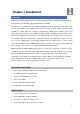
Chapter 1 Introduction 1 Overview With years of Internet telephony and router manufacturing experience, PLANET proudly introduces the latest member of the PLANET VoIP gateway family: the VIP-280. According to the feedbadks from our customers, PLANET's new VoIP gateway, the VIP-280, not only provides high quality voice communications, but also offers secured, reliable Internet sharing capabilities for either daily voice or Internet communications.
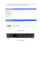
• Voice processing: Voice Active Detection, DTMF detection/ generation, G.168 echo cancellation (16mSec.), Comfort noise generation, Call progress detection, Gain Control Package Content The contents of your product should contain the following items: H.323/SIP VoIP router Power adapter Quick Installation Guide User’s Manual CD RJ-11 cable x 2 Physical Details The following figure illustrates the front/rear panel of VIP-280.
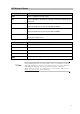
LED Display & Button LED Indicators Descriptions PWR Power is supplied to the VoIP router SYS System LED will be ON when the registration toward the GK/SIP proxy is successful Orange: the VoIP router is connected to WAN at 10Mb/s. WAN Green: the VoIP router is connected to WAN at 100Mb/s. LAN 1 ~ LAN 4 Orange: the VoIP router is connected to LAN at 10Mb/s. Green: the VoIP router is connected to LAN at 100Mb/s. Phone 1 ~ Phone 2 Off: the line is idle. On: the line is being used.
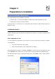
Chapter 2 2 Preparations & Installation Physical Installation Requirement This chapter illustrates basic installation of VIP-280 • Network cables. Use standard 10/100BaseT network (UTP) cables with RJ45 connectors. • TCP/IP protocol must be installed on all PCs.
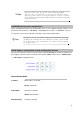
ÍNote Please locate your PC in the same network segment (192.168.0.x) of VIP-280. If you’re not familiar with TCP/IP, please refer to related chapter on user’s manual CD or consult your network administrator for proper network configurations. LAN/WAN Interface quick configurations Nature of PLANET VIP-280 is an IP Sharing (NAT) device, it comes with two default IP addresses, and default LAN side IP address is “192.168.0.1”, default WAN side IP address is “172.16.0.1”.
Default: 192.168.0.1 L Hint It is suggested to keep the DHCP server related parameters in default state to keep machine in best performance. After confirming the modification you’ve done, Please click on the Modify button to make the changes effective. WAN IP address configuration via web configuration interface Execute your web browser, and insert the IP address (default: 172.16.0.1) of VIP in the adddress bar.
after you modify the parameters.
3 Chapter 3 Network Service Configurations Configuring and monitoring your VIP-280 from web browser The VIP-280 integrates a web-based graphical user interface that can cover most configurations and machine status monitoring. Via standard, web browser, you can configure and check machine status from anywhere around the world. Overview on the web interface of VIP-280 With web graphical user interface, you may have: More comprehensive setting feels than traditional command line interface.
VIP-280 main page 14
4 Chapter 4 VoIP Configurations VIP-280 Status This page main display the current and last time VoIP call status & result. Parameter Description PC Time will show the date & time that your connected PC now. Gateway Time will show the date & time of this VoIP router, the date amd time is get from SNTP server. You may setting the SNTP server from “System Config Administrator Date & Time” Ports Message Port Type display FXS interfase the port number.
This VoIP router can register to 4 GK/SIP proxy simultaneously. Users Register Sever Status can setup the GK/SIP proxy information on “VoIP Config Register Server” Error Message For some reason (ex. All lines of this VoIP router are busy), here will display the failure information of last time VoIP Call in. Line Setting This page will setup the phone line information each port. Parameter Description Port Interface Name Line Number display FXS interfase the port number.
When Enable, it will allow you to make a VoIP call without Key in any Hotline number. That mean it will direct call out by VoIP when you off hook the phone of this line. Tone Setting This page defines the tones generated to the phone connected to the phone port. All lines use same tone parameters. After modify the tone parameters, you must save modify then Reboot to let the modified parameters work. Parameter Description Use the parameters to automatic detect cadence busy tone.
VoIP Call Out This page defines the routing rule for Call out to VoIP. (User key in the phone number through phone set dial pad, then VoIP router translate the phone number by the routing table setting here to destination IP, and dial out number then call out via network protocol).
matched with the rule will call out by this rule define. Please Notify there is a compare order rule on this routing table. That mean the VoIP router will check the rule list from top to bottom one by one, any rule item matched with the prefix digits that user key in will go to call out directly no regard to the rest rules below. For Example, if a rule item for area code 8862 is on Index 5, another rule item for area code 886 on Index 6 below that will be ignored.
002886222199518. Another example, if user key in the number is 90, STRIP field is setting to 2, and the PREFIX field is setting to 0,22199518, the actually call out number will be 0,22199518 ( “, “ mean wait 1 second). This example is especially for speed dial function. Define the optional special call out parameters on this destination. Profile Please input the name you Udefined on the profile (Please refer to the “VoIP Config Routing Setup Routing Profile”) list.
line and number to dial out. Parameter Description Define the Prefix number this rule service, any VoIP called from network dialed number prefix digits matched with the rule will call out to phone by this rule define. Please Notify there is a compare order rule on this Area Code routing table. That mean the VoIP router will check the rule list from top to bottom one by one, any rule item matched with the prefix digits that user key in will go to call out directly no regard to the rest rules below.
call will ring the dedicate phone line that assigned with matched number. Assign which server to authorize this incoming VoIP call before call out. Server For example, if the dial number should be checked by server 1 setting on the “Regster Server” menu (Please refer to the “VoIP Config Register Sever”).
Please remember to press the modify button to take it effect. For store back to flash memory, please press “Save Modification” (Plaase refer to the “Syetem Maintenance Save Modification”). Call Setup This page defines the optional special VoIP parameters when making/received a VoIP call.
T.38 FAX Relay ON: FAX will be transmitted by using T.38 FAX over IP protocol. OFF: FAX over IP is disable. Select the voice payload frame on each UDP package VoIP transmit. Package Frame More frames into one package is save more bandwidth. The default frames on each package is 3. Q.931 Fast Start ON: Enable Fast Start capability during Q.931 handshaking. OFF: Disable Fast Start capability during Q.931 handshaking. User defines ID #1 during this VoIP call. ID1 E.164: Parameter on ID1 field is the E.
Line busy No answer Please add a profile at “VoIP Config Call Routing Call out Routing table (Please refer to the “VoIP Config Call Setup” and put the name of profile on the Call Routing /VoIP Call Out”). Parameter Description Define the forward IP and forward phone number when there is no match rule setting on “VoIP Call Out Routing” table. The format is Other IP/phone number or URL/phone number. I.e.
Register Server If this VoIP router want to use GK/SIP proxy service to transfer the VoIP call, you can input the GK /SIP information here. The VoIP router can register to up to four GK/SIP proxy simultaneously. Parameter Description Success: Register successful. Register Server Status Failure: Register failure. Disable: disable register this GK/SIP proxy server MAC SR1~SR4 Remark Display the MAC address of WAN on this VoIP router Enable: Enable the VoIP router to register Server #1.
L Hint When voice communication is established via H.323 protocol, please add a ”h323:” in front of the IP address. Such as: the GK IP address is 192.168.0.100, then input “h323:192.168.0.100” in the IP address. When voice communication via the SIP protocol, please add a “sip:” in front of the IP address/URL. Such as: the SIP-50 IP address is 192.168.0.50, then input “sip:192.168.0.50” in the IP address. Please remember to press the “Done” button to take it effect.
Parameter Description Show the IP of this VoIP router Gateway IP Select the name you want to make connect, this is defined on Web Call Name page. (Please refer to the “VoIP Config Web Call Setting Web call). Call Press to make a call. Stop Stop the call. WebCall Config This page let you define the welcome message, LOGO, call number when using Web Call function. Web Call accept List: Define the display name on select option during Web call.
name, please rename your logo graphic file(.bmp, .jpg, .gif) to “Welcome” before upload. There is a file size limitation. Please press the Browse button to select the “Welcome” file you want to upload and press Upload to Upload it. Delete Delete this rule item on routing table. Stop Stop the call. Set Welcome page: Set up the authorization check option for Web Call function. When Enable the authorization check, user need to input the valid user name and password to use the Web Call function.
Chapter 5 5 System Configurations System Config Bridge Mode Setting This page allows you to disable/enable this device become bridge device or not. When it becomes a bridge device, bridge interface use LAN's IP address, LAN's subnet mask. When working on Bridge Mode, the VoIP router will use only the LAN setting IP, The VoIP router will use the same LAN IP setting as WAN IP. That mean, When Bridge mode enable, the WAN connection setting will be ignored.
Basic Settings: You can configure basic firewall settings in this router. LAN-to-WAN Access Rules: You can define LAN-to-WAN network access rules which evaluate the network traffic's source IP address, destination IP address, and communication port to decide if it's allowed to pass through the firewall.
WAN to LAN Access Rules This pages allows you to define WAN-to-LAN network access rules which evaluate the network traffic's source IP address, destination IP address, and communication port to decide if it's allowed to pass through the firewall. By default, the stateful packet inspection module of this router blocks all traffic to the LAN that originates from the Internet.
DHCP Server Setting This page allows you to set up configurations of DHCP server built in the router. The DHCP server of this router provides IP addresses, the subnet mask, the gateway address, and DNS server addresses to the LAN computers and devices dynamically. The default IP address space of this DHCP server is 192.168.0.x, with subnet mask 255.255.255.0, and the default gateway of this network is the IP address of this router (192.168.0.1).
Virtual Server This page allows you to map a TCP or a UDP port of the router to a host which actually deals with requests on the private network. DMZ This page let you set up the DMZ service on the VoIP router.
System Maintenance This page let you backup / Restore all of your configuration parameters on the VoIP router. It is very good idea to back up all of your VoIP router configuration parameters after install. Configurations To Backup, press Download setting backup file, and input the file name you want and file location to save. To Restore, press the Browse button the select the backup configuration parameters file to upload then press Restore .
Reboot System Use the Reboot button on this page to reboot your VoIP router, before you reboot, please make sure you have to press the “Saved modification” to save your current configuration to Flash ROM, otherwise all the change will be disappear after reboot.
Appendix A Voice communications A There are several ways to make calls to desired destination in VIP-280. In this chapter, we’ll lead you step by step to establish your first voice communication via web browsers operations. Default Configuration Without any configuration, your VIP-280 is come with following basic information.
Supposing you have one VIP-280 connects to four telephones, just pick up phone 1 and dial ‘202’, phone 2 should rings. 202 VIP-280 local port #2 Line number: 201 ))) Line number: 202 Peer-to-Peer (P2P) mode H.323 IP Phone IP Address: 172.16.0.100 Number: 1001 VIP-280 SIP IP Phone WAN IP Address: 172.16.0.1 IP Address: 172.16.0.200 Number: 7001 Number: 2001 VIP-280 configurations: STEP 1: Please log in machine via web browser, and select Line Setting in the Line config menu.
STEP 2: Select VoIP Call Out in the Call Routing menu; insert the values of the index number, Area Code and IP Address on the VoIP call out routing table for outgoing calls. The sample configuration screen is shown below. L Hint When the calling party is an a ”h323:” in front of the IP Such as: the destination H.323 input “h323:172.16.0.100” in VIP-320/VIP-280 VoIP Callout H.323 device, please add address. device is 172.16.0.
Voice communication via SIP proxy server –SIP50 Registration / Registration / Authentication Authentication SIP-50 IP Address: 172.16.0.50 VIP-280 IP Address: 172.16.0.28 VIP-320 IP Address: 172.16.0.32 Line Number: 280 Line Number: 320 Machine configurations on the VIP-280: STEP 1: Please log in machine via web browser, and select Register Server setting in the VoIP Config menu.
STEP 2: Select Line Setting in the Line config menu. In this Line Setting page, please insert the telephone number assigned to this line, and then the sample configuration screen is shown below (in this sample, we’re using number 280 for incoming calls). STEP 3: If wants to assign the individual voice codec (G.723.1/G.729/G.
STEP 5: Repeat the same configuration steps on the VIP-320, and check the machine registration status, make sure the registrations are completed. ====================================================== Test the scenario: To verify the VoIP communication, you may make calls from SIP client (VIP-280) 280 to the SIP client (VIP-320) 320 or reversely make calls from SIP client (VIP-320) 320 to the SIP client (VIP-280) 280.
Appendix B VIP-280 Specifications Product Model Hardware WAN LAN FXS Standards and protocol Standard Voice codec Voice Standard Supplementary services Protocols Internet features H.323/ SIP VoIP Router VIP-280 B 1 x 10/100Mbps RJ-45 port 4 x 10/100Mbps RJ-45 port 2 x RJ-11 connection H.323 version v2/v3,H.323 Fast start, and H.245 DTMF relay, SIP 2.0 (RFC3261) G.723.1 (6.3k/5.3k), G.729A, G.