Networking & Communication Broadband VPN Router VRT-401 User’s Manual
Copyright Copyright (C) 2002 PLANET Technology Corp. All rights reserved. The products and programs described in this User’s Manual are licensed products of PLANET Technology, This User’s Manual contains proprietary information protected by copyright, and this User’s Manual and all accompanying hardware, software, and documentation are copyrighted.
Table of Contents CHAPTER 1 INTRODUCTION ...................................................................................... 1 VRT-401 Features .................................................................................................. 1 Package Contents ................................................................................................. 3 Physical Details ..................................................................................................... 4 CHAPTER 2 INSTALLATION ...
Examples.............................................................................................................. 83 Using Certificates.............................................................................................. 101 CHAPTER 9 OTHER FEATURES AND SETTINGS ................................................. 106 Overview ............................................................................................................ 106 PC Database ...............................................
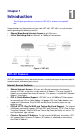
1 Chapter 1 Introduction This Chapter provides an overview of VRT-401's features and capabilities. Congratulations on the purchase of your new VRT-401. VRT-401 is a multi-function device providing the following services: • • Shared Broadband Internet Access for all LAN users. 4-Port Switching Hub for 10BaseT or 100BaseT connections. Figure 1: VRT-401 VRT-401 Features VRT-401 incorporates many advanced features, carefully designed to provide sophisticated functions while being easy to use.
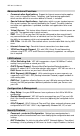
VRT-401 User Manual Advanced Internet Functions • Communication Applications. Support for Internet communication applications, such as interactive Games, Telephony, and Conferencing applications, which are often difficult to use when behind a Firewall, is included. • Special Internet Applications. Applications which use non-standard connections or port numbers are normally blocked by the Firewall.
Introduction tion and even the existence of each PC is hidden. From the external viewpoint, there is no network, only a single device - VRT-401. • Stateful Inspection Firewall. All incoming data packets are monitored and all incoming server requests are filtered, thus protecting your network from malicious attacks from external sources. • Protection against DoS attacks.
VRT-401 User Manual Physical Details Front-mounted LEDs Figure 2: Front Panel Power On - Power on. Off - No power. Status (Red) On - Error condition. Off - Normal operation. Blinking - This LED blinks during start up. LAN For each port, there are 2 LEDs • • WAN LNK/ACT • On - Corresponding LAN port is active. • Off - No active connection on the corresponding LAN port. • Flashing - Data is being transmitted or received via the corresponding LAN port.
Introduction Rear Panel Figure 3: Rear Panel DMZ Use a standard LAN cable to connect a normal port on the other hub. Reset Button This button has two (2) functions: • Reboot. When pressed and released, VRT-401 will reboot (restart). • Clear All Data. This button can also be used to clear ALL data and restore ALL settings to the factory default values. To Clear All Data and restore the factory default values: 1. Power Off. 2. Hold the Reset Button down while you Power On. 3.
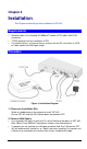
Chapter 2 Installation This Chapter covers the physical installation of VRT-401. Requirements • Network cables. Use standard 10/100BaseT network (UTP) cables with RJ45 connectors. • TCP/IP protocol must be installed on all PCs. • For Internet Access, an Internet Access account with an ISP, and either of a DSL or Cable modem (for WAN port usage) Procedure Figure 4: Installation Diagram 1. Choose an Installation Site Select a suitable place on the network to install VRT-401.
Installation • If desired, connect the DMZ port to a standard port on a Hub. PCs connected to this hub will also gain Internet access, but will NOT be able to access the rest of the LAN. 3. Connect WAN Cable Connect the DSL or Cable modem to the WAN port on VRT-401. Use the cable supplied with your DSL/Cable modem. If no cable was supplied, use a standard cable. 4. Power Up • Power on the Cable or DSL modem. • Connect the supplied power adapter to VRT-401 and power up.
3 Chapter 3 Setup This Chapter provides Setup details of VRT-401. Overview This chapter describes the setup procedure for: • Internet Access • LAN configuration PCs on your local LAN may also require configuration. For details, see Chapter 4 - PC Configuration. Other configuration may also be required, depending on which features and functions of VRT-401 you wish to use. Use the table below to locate detailed instructions for the required functions. To Do this: Refer to: Configure PCs on your LAN.
Setup Configure or use any of the following: • PC Database • Remote Admin • Routing (RIP and static Routing) • Upgrade firmware • Enable/Disable UPnP Support Chapter 9: Other Features and Settings Where use of a certain feature requires that PCs or other LAN devices be configured, this is also explained in the relevant chapter. Configuration Program VRT-401 contains an HTTP server. This enables you to connect to it, and configure it, using your Web Browser. Your Browser must support JavaScript.
VRT-401 User Manual 2. Start your WEB browser. 3. In the Address box, enter "HTTP://" and the IP Address of VRT-401, as in this example, which uses VRT-401’s default IP Address: HTTP://192.168.0.1 If you can't connect If VRT-401 does not respond, check the following: • VRT-401 is properly installed, LAN connection is OK, and it is powered ON. You can test the connection by using the "Ping" command: • Open the MS-DOS window or command prompt window. • Enter the command: ping 192.168.0.
Setup Config Wizard The first time you connect to VRT-401, the Config Wizard will run automatically. (The Setup Wizard will also run if VRT-401’s default settings are restored.) 1. Step through the Wizard until finished. • You need to know the type of Internet connection service used by your ISP. Check the data supplied by your ISP. • The common connection types are explained in the tables below. 2. On the final screen of the Wizard, run the test and check that an Internet connection can be established.
VRT-401 User Manual PPTP Mainly used in Europe. • PPTP Server IP Address. You connect to the ISP only when required. The IP address is usually allocated automatically, but may be Static (Fixed). • User name and password. • IP Address allocated to you, if Static (Fixed). Other Modems (e.g. Broadband Wireless) Type Details ISP Data required Dynamic IP Address Your IP Address is allocated automatically, when you connect to you ISP. Usually, none.
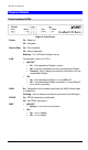
Setup Home Screen After finishing or exiting the Setup Wizard, you will see the Home screen. When you connect in future, you will see this screen when you connect. An example screen is shown below. Figure 6: Home Screen Navigation & Data Input • Use the menu bar on the top of the screen, and the "Back" button on your Browser, for navigation. • Changing to another screen without clicking "Save" does NOT save any changes you may have made.
VRT-401 User Manual LAN Screen Use the LAN link on the main menu to reach the LAN screen An example screen is shown below. Figure 7: LAN Screen Data - LAN Screen TCP/IP IP Address IP address for VRT-401, as seen from the local LAN. Use the default value unless the address is already in use or your LAN is using a different IP address range. In the latter case, enter an unused IP Address from within the range used by your LAN. Subnet Mask The default value 255.255.255.
Setup DHCP What DHCP Does A DHCP (Dynamic Host Configuration Protocol) Server allocates a valid IP address to a DHCP Client (PC or device) upon request. • The client request is made when the client device starts up (boots). • The DHCP Server provides the Gateway and DNS addresses to the client, as well as allocating an IP Address. • VRT-401 can act as a DHCP server. • Windows 95/98/ME and other non-Server versions of Windows will act as a DHCP client.
Chapter 4 PC Configuration 4 This Chapter details the PC Configuration required on the local ("Internal") LAN. Overview For each PC, the following may need to be configured: • TCP/IP network settings • Internet Access configuration Windows Clients This section describes how to configure Windows clients for Internet access via VRT401. The first step is to check the PC's TCP/IP settings.
PC Configuration Checking TCP/IP Settings - Windows 9x/ME: 1. Select Control Panel - Network. You should see a screen like the following: Figure 8: Network Configuration 2. Select the TCP/IP protocol for your network card. 3. Click on the Properties button. You should then see a screen like the following. Figure 9: IP Address (Win 95) Ensure your TCP/IP settings are correct, as follows: Using DHCP To use DHCP, select the radio button Obtain an IP Address automatically.
VRT-401 User Manual • On the Gateway tab, enter VRT-401’s IP address in the New Gateway field and click Add, as shown below. Your LAN administrator can advise you of the IP Address they assigned to VRT-401. Figure 10: Gateway Tab (Win 95/98) • On the DNS Configuration tab, ensure Enable DNS is selected. If the DNS Server Search Order list is empty, enter the DNS address provided by your ISP in the fields beside the Add button, then click Add.
PC Configuration Checking TCP/IP Settings - Windows NT4.0 1. Select Control Panel - Network, and, on the Protocols tab, select the TCP/IP protocol, as shown below. Figure 12: Windows NT4.0 - TCP/IP 2. Click the Properties button to see a screen like the one below.
VRT-401 User Manual Figure 13: Windows NT4.0 - IP Address 3. Select the network card for your LAN. 4. Select the appropriate radio button - Obtain an IP address from a DHCP Server or Specify an IP Address, as explained below. Obtain an IP address from a DHCP Server This is the default Windows setting. Using this is recommended. By default, VRT401 will act as a DHCP Server. Restart your PC to ensure it obtains an IP Address from VRT-401.
PC Configuration Figure 14 - Windows NT4.0 - Add Gateway 2. The DNS should be set to the address provided by your ISP, as follows: • Click the DNS tab. • On the DNS screen, shown below, click the Add button (under DNS Service Search Order), and enter the DNS provided by your ISP.
VRT-401 User Manual Figure 15: Windows NT4.
PC Configuration Checking TCP/IP Settings - Windows 2000: 1. Select Control Panel - Network and Dial-up Connection. 2. Right - click the Local Area Connection icon and select Properties. You should see a screen like the following: Figure 16: Network Configuration (Win 2000) 3. Select the TCP/IP protocol for your network card. 4. Click on the Properties button. You should then see a screen like the following.
VRT-401 User Manual Figure 17: TCP/IP Properties (Win 2000) 5. Ensure your TCP/IP settings are correct, as described below. Using DHCP To use DHCP, select the radio button Obtain an IP Address automatically. This is the default Windows setting. Using this is recommended. By default, VRT-401 will act as a DHCP Server. Restart your PC to ensure it obtains an IP Address from VRT-401.
PC Configuration Checking TCP/IP Settings - Windows XP 1. Select Control Panel - Network Connection. 2. Right click the Local Area Connection and choose Properties. You should see a screen like the following: Figure 18: Network Configuration (Windows XP) 3. Select the TCP/IP protocol for your network card. 4. Click on the Properties button. You should then see a screen like the following.
VRT-401 User Manual Figure 19: TCP/IP Properties (Windows XP) 5. Ensure your TCP/IP settings are correct. Using DHCP To use DHCP, select the radio button Obtain an IP Address automatically. This is the default Windows setting. Using this is recommended. By default, VRT-401 will act as a DHCP Server. Restart your PC to ensure it obtains an IP Address from VRT-401.
PC Configuration Internet Access To configure your PCs to use VRT-401 for Internet access: • Ensure that the DSL modem, Cable modem, or other permanent connection is functional. • Use the following procedure to configure your Browser to access the Internet via the LAN, rather than by a Dial-up connection. For Windows 9x/ME/2000 1. Select Start Menu - Settings - Control Panel - Internet Options. 2. Select the Connection tab, and click the Setup button. 3.
VRT-401 User Manual Macintosh Clients From your Macintosh, you can access the Internet via VRT-401. The procedure is as follows. 1. Open the TCP/IP Control Panel. 2. Select Ethernet from the Connect via pop-up menu. 3. Select Using DHCP Server from the Configure pop-up menu. The DHCP Client ID field can be left blank. 4. Close the TCP/IP panel, saving your settings.
Chapter 5 Operation and Status 5 This Chapter details the operation of VRT-401 and the status screens. Operation Once both VRT-401 and the PCs are configured, operation is automatic. However, there are some situations where additional Internet configuration may be required: • If using Internet-based Communication Applications, it may be necessary to specify which PC receives an incoming connection. Refer to Chapter 6 - Internet Features for further details.
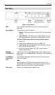
VRT-401 User Manual Data - Status Screen Internet Connection Method This indicates the current connection method, as set in the Setup Wizard. Broadband Modem This shows the connection status of the modem. Internet Connection Current connection status: • Active • Idle • Unknown • Failed If there is an error, you can click the "Connection Details" button to find out more information. Internet IP Address This IP Address is allocated by the ISP (Internet Service Provider).
Operation and Status Connection Status - PPPoE If using PPPoE (PPP over Ethernet), a screen like the following example will be displayed when the "Connection Details" button is clicked. Figure 21: PPPoE Status Screen Data - PPPoE Screen Connection Physical Address The hardware address of this device, as seen by remote devices on the Internet. (This is different to the hardware address seen by devices on the local LAN.) IP Address The IP Address of this device, as seen by Internet users.
VRT-401 User Manual Connection Log Connection Log • The Connection Log shows status messages relating to the existing connection. • The most common messages are listed in the table below. • The "Clear Log" button will restart the Log, while the Refresh button will update the messages shown on screen. Buttons Connect If not connected, establish a connection to your ISP. Disconnect If connected to your ISP, hang up the connection. Clear Log Delete all data currently in the Log.
Operation and Status Error: Invalid or unknown packet type The data received from the ISP's Server could not be processed. This could be caused by data corruption (from a bad link), or the Server using a protocol which is not supported by this device.
VRT-401 User Manual Connection Status - PPTP If using PPTP (Peer-to-Peer Tunneling Protocol), a screen like the following example will be displayed when the "Connection Details" button is clicked. Figure 22: PPTP Status Screen Data - PPTP Screen Connection Physical Address The hardware address of this device, as seen by remote devices on the Internet. (This is different to the hardware address seen by devices on the local LAN.) IP Address The IP Address of this device, as seen by Internet users.
Operation and Status Buttons Connect If not connected, establish a connection to your ISP. Disconnect If connected to your ISP, hang up the connection. Clear Log Delete all data currently in the Log. This will make it easier to read new messages. Refresh Update the data on screen. Connection Status - Telstra Big Pond An example screen is shown below.
VRT-401 User Manual Connection Status This indicates whether or not the connection is currently established. • If the connection does not exist, the "Connect" button can be used to establish a connection. • If the connection currently exists, the "Disconnect" button can be used to break the connection. • Normally, it is not necessary to use the Connect and Disconnect buttons unless the setting "Connect automatically, as required" is disabled.
Operation and Status Data - SingTel RAS Screen Internet RAS Plan The RAS Plan which is currently used. Physical Address The hardware address of this device, as seen by remote devices on the Internet. (This is different to the hardware address seen by devices on the local LAN.) IP Address The IP Address of this device, as seen by Internet users. This address is allocated by your ISP (Internet Service Provider). Network Mask The Network Mask associated with the IP Address above.
VRT-401 User Manual Connection Details - Fixed/Dynamic IP Address If your access method is "Direct" (no login), a screen like the following example will be displayed when the "Connection Details" button is clicked. Figure 25: Connection Details - Fixed/Dynamic IP Address Data - Fixed/Dynamic IP address Screen Internet Physical Address The hardware address of this device, as seen by remote devices on the Internet. (This is different to the hardware address seen by devices on the local LAN.
Operation and Status Buttons Release/Renew Button will display EITHER "Release" OR "Renew" Refresh This button is only useful if the IP address shown above is allocated automatically on connection. (Dynamic IP address). If you have a Fixed (Static) IP address, this button has no effect. • If the ISP's DHCP Server has NOT allocated an IP Address for VRT-401, this button will say "Renew".
Chapter 6 Internet Features 6 This Chapter explains when and how to use VRT-401’s "Internet" Features. Overview The following advanced features are provided. • Advanced Internet • Communication Applications • Special Applications • DMZ • URL filter • Dynamic DNS • Virtual Servers • Options Advanced Internet Screen Figure 26: Internet Screen This screen allows configuration of all advanced features relating to Internet access.
Internet Features Communication Applications Most applications are supported transparently by VRT-401. But sometimes it is not clear which PC should receive an incoming connection. This problem could arise with the Communication Applications listed on this screen. If this problem arises, you can use this screen to set which PC should receive an incoming connection, as described below.
VRT-401 User Manual Figure 27: Special Applications Screen Data - Special Applications Screen Checkbox Use this to Enable or Disable this Special Application as required. Name Enter a descriptive name to identify this Special Application. Incoming Ports Outgoing Ports • Type - Select the protocol (TCP or UDP) used when you receive data from the special application or service. (Note: Some applications use different protocols for outgoing and incoming data).
Internet Features If an application still cannot function correctly, try using the "DMZ" feature. DMZ This feature, if enabled, allows one (1) computer on your LAN to be exposed to all users on the Internet, allowing unrestricted 2-way communication between the "DMZ PC" and other Internet users or Servers. • This allows almost any application to be used on the "DMZ PC". • The "DMZ PC" will receive all "Unknown" connections and data.
VRT-401 User Manual URL Filter Screen Click the "Configure URL Filter" button on the Advanced Internet screen to access the URL Filter screen. An example screen is shown below. Figure 28: URL Filter Screen Data - URL Filter Screen Filter Strings Current Entries This lists any existing entries. If you have not entered any values, this list will be empty. Add Filter String To add an entry to the list, enter it here, and click the "Add" button. An entry may be a Domain name (e.g. www.trash.
Internet Features Dynamic DNS (Domain Name Server) This free service is very useful when combined with the Virtual Server feature. It allows Internet users to connect to your Virtual Servers using a URL, rather than an IP Address. This also solves the problem of having a dynamic IP address. With a dynamic IP address, your IP address may change whenever you connect, which makes it difficult to connect to you. The Service works as follows: 1. You must register for the service at http://www.dyndns.
VRT-401 User Manual Data - Dynamic DNS Screen DDNS Service DDNS Service • You must sign up first to create a new account before using the service. The service is free. • Click this link to connect to the www.dyndns.org Web site. • Your initial password will be E-mailed to you; you can change this later if you wish. • After registration, use the "Create New Host" link (on the www.dyndns.org Web site) to request a domain name. DDNS Data User Name Enter the "User name" specified at the www.dyndns.
Internet Features Virtual Servers This feature allows you to make Servers on your LAN accessible to Internet users. Normally, Internet users would not be able to access a server on your LAN because: • Your Server does not have a valid external IP Address. • Attempts to connect to devices on your LAN are blocked by the firewall in this device. The "Virtual Server" feature solves these problems and allows Internet users to connect to your servers, as illustrated below.
VRT-401 User Manual Using the DMZ port for Virtual Servers You should connect your Virtual Servers to the DMZ port, for the following reasons: • Traffic passing between the DMZ and LAN passes through the firewall. The firewall will protect your LAN if your Server is compromised and used to launch an attack on your LAN. • For each enabled Virtual Server, a firewall rule to allow incoming traffic from the Internet (WAN) to the DMZ is automatically created.
Internet Features Defining your own Virtual Servers If the type of Server you wish to use is not listed on the Virtual Servers screen, you can use the Firewall Rules to allow particular incoming traffic and forward it to a specified PC (Server). Connecting to the Virtual Servers Once configured, anyone on the Internet can connect to your Virtual Servers. They must use the Internet IP Address (the IP Address allocated to you by your ISP). e.g. http://203.70.212.52 ftp://203.70.212.
VRT-401 User Manual MTU MTU size MTU (Maximum Transmission Unit) value should only be changed if advised to do so by Technical Support. • Enter a value between 1 and 1500. • This device will still auto-negotiate with the remote server, to set the MTU size. The smaller of the 2 values (autonegotiated, or entered here) will be used. • For direct connections (not PPPoE or PPTP), the MTU used is always 1500.
Chapter 7 Security Configuration 7 This Chapter explains the settings available via the security configuration section of the "Security" menu. Overview The following advanced configurations are provided. • Admin Login • Access Control • Firewall Rules • Logs • Security Options • Scheduling • Services Admin Login The Admin Login screen allows you to assign a user name and password to VRT-401. Figure 33: Admin Login Screen 1. The default login name is "admin".
VRT-401 User Manual Figure 34: Password Dialog Enter the "User Name" and "Password" you set on the Admin Login screen above.
Security Configuration Access Control This feature is accessed by the Access Control link on the Security menu. The Access Control feature allows administrators to restrict the level of Internet Access available to PCs on your LAN. With the default settings, everyone has unrestricted Internet access. To use this feature: 1. Set the desired restrictions on the "Default" group. All PCs are in the "Default" group unless explicitly moved to another group. 2.
VRT-401 User Manual Data - Access Control Screen Group Group Select the desired Group. The screen will update to display the settings for the selected Group. Groups are named "Default", "Group 1", "Group 2", "Group 3" and "Group 4", and cannot be re-named. "Members" Button Click this button to add or remove members from the current Group. • If the current group is "Default", then members can not be added or deleted. This group contains PCs not allocated to any other group.
Security Configuration View Log Click this to open a sub-window where you can view the "Access Control" log. This log shows attempted Internet accesses which have been blocked by the Access Control feature. Clear Log Click this to clear and restart the "Access Control" log, making new entries easier to read.
VRT-401 User Manual Group Members Screen This screen is displayed when the Members button on the Access Control screen is clicked. Figure 36: Group Members Use this screen to add or remove members (PCs) from the current group. • The "Del >>" button will remove the selected PC (in the Members list) from the current group. • The "<< Add" button will add the selected PC (in the Other PCs list) to the current group. PCs not assigned to any group will be in the "Default" group.
Security Configuration 57
VRT-401 User Manual Firewall Rules For normal operation and LAN protection, it is not necessary to use this screen. The Firewall will always block DoS (Denial of Service) attacks. A DoS attack does not attempt to steal data or damage your PCs, but overloads your Internet connection so you can not use it - the service is unavailable. As well, you can use this screen to create Firewall rules to block or allow specific traffic. But Incorrect configuration may cause serious problems.
Security Configuration Data - Firewall Rules Screen Rule List View Rules for .. Select the desired option; the screen will update and list any current rules. If you have not defined any rules, the list will be empty. Data For each rule, the following data is shown: • Name - The name you assigned to the rule. • Source - The traffic covered by this rule, defined by the source IP address. If the IP address is followed by ... this indicates there is range of IP addresses, rather than a single address.
VRT-401 User Manual Define Firewall Rule Clicking the "Add" button in the Firewall Rules screen will display a screen like the example below. Figure 38: Define Firewall Rule Data - Define Firewall Rule Screen Name Enter a suitable name for this rule. Type This determines the source and destination ports for traffic covered by this rule. Select the desired option. Source IP These settings determine which traffic, based on their source IP address, is covered by this rule.
Security Configuration Dest IP These settings determine which traffic, based on their destination IP address, is covered by this rule. Select the desired option: • Any - All traffic from the source port is covered by this rule. • Single address - Enter the required IP address in the "Start IP address" field". You can ignore the "Subnet Mask" field. • Range address - If this option is selected, you must complete both the "Start IP address" and "Finish IP address" fields.
VRT-401 User Manual Logs The Logs record various types of activity on VRT-401. This data is useful for troubleshooting, but enabling all logs will generate a large amount of data and adversely affect performance. Since only a limited amount of log data can be stored in VRT-401, log data can also be E-mailed to your PC or sent to a Syslog Server.
Security Configuration Access Control If enabled, the log will include attempted outgoing connections which have been blocked by the "Access Control" feature. Firewall Rules If enabled, the log will details of packets blocked by userdefined Firewall rules. Logging can be set for each rule individually. Only rules which have logging enabled will be included. VPN If enabled, the VPN log will record incoming and outgoing VPN connections. Timezone Select the correct Timezone for your location.
VRT-401 User Manual Include Select the logs you wish to be included.
Security Configuration Security Options This screen allows you to set Firewall and other security-related options. Figure 40: Security Options Screen Data - Security Options Screen SPI Firewall Enable DoS Firewall If enabled, DoS (Denial of Service) attacks will be detected and blocked. The default is enabled. It is strongly recommended that this setting be left enabled.
VRT-401 User Manual Options Respond to ICMP Allow IPsec Allow PPTP Allow L2TP Allow TFTP firmware upgrade The ICMP protocol is used by the "ping" and "trace route" programs, and by network monitoring and diagnostic programs. • If checked, VRT-401 will respond to ICMP packets received from the Internet. • If not checked, ICMP packets from the Internet will be ignored. Disabling this option provides a slight increase in security.
Security Configuration Scheduling • This schedule can be (optionally) applied to any Access Control Group. • Blocking will be performed during the scheduled time (between the "Start" and "Finish" times.) • Two (2) separate sessions or periods can be defined. • Times must be entered using a 24 hr clock. • If the time for a particular day is blank, no action will be performed. Define Schedule Screen This screen is accessed by the Scheduling link on the Security menu.
VRT-401 User Manual Services Services are used in defining traffic to be blocked or allowed by the Access Control or Firewall Rules features. Many common Services are pre-defined, but you can also define your own services if required. To view the Services screen, select the Services link on the Security menu. Figure 42: Services Screen Data - Services Screen Available Services Available Services This lists all the available services. "Delete" button Use this to delete any Service you have added.
Security Configuration service. Buttons Delete Delete the selected service from the list. Add Add a new entry to the Service list, using the data shown in the "Add New Service" area on screen. Cancel Clear the " Add New Service " area, ready for entering data for a new Service.
Chapter 8 VPN 8 This Chapter describes the VPN capabilities and configuration required for common situations. Overview This section describes the VPN (Virtual Private Network) support provided by your VRT-401. A VPN (Virtual Private Network) provides a secure connection between 2 points, over an insecure network - typically the Internet. This secure connection is called a VPN Tunnel. There are many standards and protocols for VPNs. The standard implemented in VRT-401 is IPSec.
VPN • Phase I is the negotiation and establishment up of the IKE connection. • Phase II is the negotiation and establishment up of the IPsec connection. Because the IKE and IPsec connections are separate, they have different SAs (security associations). Policies VPN configuration settings are stored in Policies. Each policy defines: • The address of the remote VPN endpoint • The traffic which is allowed to use the VPN connection.
VRT-401 User Manual Common VPN Situations VPN Pass-through Figure 43: VPN Pass-through Here, a PC on the LAN behind the Router/Gateway is using VPN software, but the Router/Gateway is NOT acting as a VPN endpoint. It is only allowing the VPN connection. • The PC software can use any VPN protocol supported by the remote VPN. • The remote VPN Server must support client PCs which are behind a NAT router, and so have an IP address which is not valid on the Internet.
VPN Connecting 2 LANs via VPN Figure 45: Connecting 2 VPN Gateways This allows two (2) LANs to be connected. PCs on each endpoint gain secure access to the remote LAN. • The 2 LANs MUST use different IP address ranges. • The VPN Policies at each end determine when a VPN tunnel will be established, and what systems on the remote LAN can be accessed once the VPN connection is established. • It is possible to have simultaneous VPN connections to many remote sites.
VRT-401 User Manual VPN Configuration This section covers the configuration required on VRT-401 when using Manual Key Exchange (Manual Policies) or IKE (Automatic Policies). Details of using Certificates are covered in a later section. VPN Policies Screen To view this screen, select VPN Policies from the VPN menu. This screen lists all existing VPN policies. If no policies exist, the list will be empty.
VPN Operations Add To add a new policy, click the "Add" button. See the following section for details. Edit To Edit or modify an existing policy, select it and click the "Edit" button. Move There are 2 ways to change the order of policies: • Use the up and down indicators on the right to move the selected row. You must confirm your changes by clicking "OK". If you change your mind before clicking "OK", click "Cancel" to reverse your changes.
VRT-401 User Manual • Otherwise, click Next to continue. You will see a screen like the following. Figure 48: VPN Wizard - General General Settings Policy Name Enter a suitable name. This name is not supplied to the remote VPN. It is used only to help you manage the policies. Enable Policy Enable or disable the policy as required. For each remote VPN, only 1 policy can be enabled at any time. Remote VPN Endpoint The Internet IP address of the remote VPN endpoint (Gateway or client).
VPN Figure 49: VPN Wizard - Traffic Selector • For outgoing VPN connections, these settings determine which traffic will cause a VPN tunnel to be created, and which traffic will be sent through the tunnel. • For incoming VPN connections, these settings determine which systems on your local LAN will be available to the remote endpoint. • The 2 VPN endpoints MUST use different address ranges.
VRT-401 User Manual Remote IP addresses Type • Single address - enter an IP address in the "Start IP address" field. • Range address - enter the starting IP address in the "Start IP address" field, and the finish IP address in the "Finish IP address" field. • Subnet address - enter the desired IP address in the "Start IP address" field, and the network mask in the "Subnet Mask" field. The remote VPN should have these IP addresses entered as it's "Local" addresses. 3. Click Next to continue.
VPN These settings must match the remote VPN. Note that you cannot use both AH and ESP. Manually assigned Keys AH Authentication AH (Authentication Header) specifies the authentication protocol for the VPN header, if used. (AH is often NOT used) If AH is not enabled, the following settings can be ignored. Keys • The "in" key here must match the "out" key on the remote VPN, and the "out" key here must match the "in" key on the remote VPN. • Keys can be in ASCII or Hex (0..9 A..
VRT-401 User Manual For Manual Key Exchange, configuration is now complete. • Click "Next" to view the final screen. • On the final screen, click "Finish" to save your settings, then "Close" to exit the Wizard. IKE Phase 1 If you selected IKE, the following screen is displayed after the Traffic Selector screen. Figure 51: VPN Wizard - IKE Phase 1 IKE Phase 1 (IKE SA) Direction Select the desired option: • Initiator - Only outgoing connections will be created.
VPN Authentication • RSA Signature requires that both VPN endpoints have valid Certificates issued by a CA (Certification Authority). • For Pre-shared key, enter the same key value in both endpoints. The key should be at least 8 characters (maximum is 128 characters). Note that this key is used for the IKE SA only. The keys used for the IPsec SA are automatically generated. Encryption Select the desired method, and ensure the remote VPN endpoint uses the same method.
VRT-401 User Manual IKE Phase 2 (IPsec SA) IPsec SA Life Time This setting does not have to match the remote VPN endpoint; the shorter time will be used. Although measured in seconds, it is common to use time periods of several hours, such 28,800 seconds. IPSec PFS If enabled, PFS (Perfect Forward Security) enhances security by changing the IPsec key at regular intervals, and ensuring that each key has no relationship to the previous key. Thus, breaking 1 key will not assist in breaking the next key.
VPN Examples This section describes some examples of using VRT-401 in common VPN situations. Example 1: Connecting 2 VRT-401s In this example, 2 LANs are connected via VPN. Figure 53: Connecting 2 VRT-401s Note • The LANs MUST use different IP address ranges. • Both endpoints have fixed WAN (Internet) IP addresses. Configuration Settings Setting LAN A Gateway LAN B Gateway Notes Name Policy 1 Policy 1 Name does not affect operation. Select a meaningful name. Remote Endpoint 205.17.11.
VRT-401 User Manual Pre-shared Key Xxxxxxxxxx Xxxxxxxxxx Must match IKE Authentication algorithm MD5 MD5 Must match IKE Encryption DES DES Must match IKE Exchange mode Main Mode Main Mode Must match DH Group Group 1 (768 bit) Group 1 (768 bit) Must match IKE SA Life time 28800 28800 Does not have to match. Shorter period will be used. IKE PFS Disable Disable Must match IPSec SA Parameters IPSec SA Life time 28800 28800 Does not have to match. Shorter period will be used.
VPN Example 2: Windows 2000/XP Client to LAN In this example, a Windows 2000/XP client connects to VRT-401 and gains access to the local LAN. Figure 54: Windows 2000/XP Client to VRT-401 To use 3DES encryption, you need Service Pack 3 or later installed on Windows 2000. VRT-401 Configuration Setting Value Notes Name Win Client Name does not affect operation. Select a meaningful name. Remote Endpoint 172.16.9.10 Other endpoint's WAN (Internet) IP address. Local IP addresses Subnet address: 192.
VRT-401 User Manual mode DH Group Group 1 (768 bit) Must match client PC IKE SA Life time 28800 Does not have to match client PC. Shorter period will be used. IKE PFS Disable Must match client PC IPSec SA Parameters IPSec SA Life time 28800 Do not have to match. Shorter period will be used.
VPN Figure 56: Windows 2000/XP - Policy Properties • Note that no rules are in use. Two 2 rules are required - incoming and outgoing. • The outgoing rule will be added first. 6. Deselect the "Use Add Wizard" checkbox, then click "Add" to view the screen below. Figure 57: IP Filter List 7. Type "To DUT" for the name, then click "Add" to see a screen like the following.
VRT-401 User Manual Figure 58: Filter Properties: Addressing 8. Enter the Source IP address and the Destination IP address. • Since this is the outing filter, the Source IP address is "My IP address" and the Destination IP address is the address range used on the remote LAN. • Ensure the Mirrored option is checked. 9. Click "OK" to save your settings and close this dialog. Figure 59: New Rule Properties: IP Filter List 10.
VPN Figure 60: New Rule Properties: Filter Action 11. Select Require Security, then click the "Edit" button, to view the Require Security Properties screen. Figure 61: Require Security Properties 12. Select Negotiate security (this selects IKE), then click "Add".
VRT-401 User Manual Figure 62: Modify Security Method 13. On the resulting screen (above), select High [ESP] then click "OK" to save your changes and return to the Require Security Properties screen. Figure 63: Require Security Properties 14. Ensure the following settings are correct, then click "OK" to return to the Filter Action tab of the Edit Rule Properties screen.
VPN 15. Click the Tunnel Setting tab, then select The tunnel endpoint is specified by this IP address. Enter the WAN (Internet) IP address of VRT-401, as shown below. Figure 64: Tunnel Setting 16. Click the Authentication Methods tab, then click the "Edit" to see the screen like the example below. Figure 65: Authentication Method 17. Select Use this string to protect the key exchange (preshared key), then enter your preshared key in the field provided. 18.
VRT-401 User Manual 19. Click "Close" to return to the DUT to Win2K properties screen. The "To DUT" filter should now be listed, as shown below. Figure 66: Windows 2000/XP Client to VRT-401 20. To add the second (outgoing) rule, click "Add". For the name, enter "To Win2K", then click "Add". Figure 67: Windows 2000/XP Client to VRT-401 21. Enter the Source IP address and the Destination IP address as shown below.
VPN Figure 68: Filter Properties: Addressing 22. Click "OK" to save your changes, then "Close". Figure 69: Filter List 23. Ensure the "To Win2K" filter is selected, then click the Filter Action tab.
VRT-401 User Manual Figure 70: Filter Action 24. Select Require Security, then click "Edit". On the Require Security Methods screen below, select Negotiate security. Figure 71: Security Methods 25. Click the "Add" button. On the resulting Modify Security Method screen below, select High [ESP].
VPN Figure 72: Modify Security Method 26. Click "OK" to save your changes, then click "OK" again to return to the Filter Action screen. 27. Select the Tunnel Setting tab, and enter the WAN (Internet) IP address of this PC (172.10..9.10 in this example). Figure 73: Tunnel Setting 28. Select the Authentication Methods tab, and click the "Edit" button to see the screen below.
VRT-401 User Manual Figure 74: Authentication Method 29. Select Use this string to protect the key exchange (preshared key), then enter your preshared key in the field provided. 30. Click "OK" to save your settings, then "Close" to return to the DUT to Win2K Properties screen. There should now be 2 IP Filers listed, as shown below. Figure 75: DUT to Win2K Properties 31. Select the General tab.
VPN Figure 76: Properties - General Tab 32. Click the "Advanced" button to see the screen below. Figure 77: Key Exchange Settings 33. Click the "Methods" button to see the screen below.
VRT-401 User Manual Figure 78: Key Exchange Security Methods 34. Select the first entry, and click the "Edit" button to see the following screen. Figure 79: IKE Security Algorithms 35. Select "SHA1" for Integrity Algorithm, "3DES" for Encryption algorithm, and "Low(1)" for the Diffie-Hellman Group. 36. Click "OK" to save, then "OK" again, and then "Close" to return to the Local Security Settings screen. 37. Right click the DUT to Win2K Policy and select "Assign" to make your policy active.
VPN Example 3: Windows 2000 Server to VPN Gateway In this example, a Windows 2000 Server connects to VRT-401. Users on each LAN can then gain access to the remote LAN. Figure 81: VRT-401 to Windows 2000 Server VRT-401 Configuration This is the same as for the client setup earlier, with the exception of the IP address range for the remote endpoint. Setting Single Client Server/Gateway Remote IP addresses 172.16.9.10 Subnet address: 11.5.0.0 255.255.0.
VRT-401 User Manual Windows 2000 Server Configuration Configuration is the same as for Example 2: Windows 2000/XP Client to except for specifying the Source and Destination addresses for the "Filter Properties". Instead, for both IP Filters, the Filter Properties- Addressing should be completed as follows. Figure 82: Windows 2000 Server - Addressing • The Source Address should be set to "A specific IP Subnet", and the IP address and Subnet mask set to the address range used on VRT-401's LAN.
VPN Using Certificates Certificates are used to authenticate users. Certificates are issued to you by various CAs (Certification Authorities). These Certificates are called "Self Certificates". Each CA also issues a certificate to itself. This Certificate is required in order to validate communication with the CA. These certificates are called "Trusted Certificates.
VRT-401 User Manual Adding a Trusted Certificate 1. After obtaining a new Certificate from the CA, you need to upload it to VRT-401. 2. On the "Certificates" screen, click the "Add Trusted Certificate" button to view the Add Trusted Certificate screen, shown below. Figure 84: Add Trusted Certificate 3. 4. 5. 6. Click the "Browse" button, and locate the certificate file on your PC Select the file. The name will appear in the "Certificate File" field.
VPN Subject Name This is the name which other organizations will see as the Holder (owner) of this Certificate. This should be your registered business name or official company name. Generally, all Certificates should have the same value in the Subject field. Hash Algorithm Select the desired option. Signature Algorithm Select the desired option. RSA is recommended. Signature Key Length Select the desired option. Normally, 1024 bits provides adequate security. 3.
VRT-401 User Manual Figure 87: Add Self Certificate (3) 8. Upload the Certificate: • Click the "Browse" button, and locate the certificate file on your PC • Select the file. The name will appear in the "Certificate File" field. • Click "Upload" to upload the certificate file to VRT-401. • Click "Finished" to return to the Certificate list. The new Certificate will appear in the list. CRLs CRLs are only necessary if using Certificates.
VPN Figure 89: Upload CRL 4. Upload the CRL file: • Click the "Browse" button, and locate the CRL file on your PC • Select the file. The name will appear in the "File to Upload" field. • Click "Upload" to upload the CRL file to VRT-401. • Click "Back" to return to the CRL list. The new CRL will appear in the list. 5. Use the "Delete" button to delete the previous (now outdated) CRL.
Chapter 9 Other Features and Settings 9 This Chapter explains the screens and settings available via the "Miscellaneous" menu. Overview Normally, it is not necessary to use these screens, or change any settings. These screens and settings are provided to deal with non-standard situations, or to provide additional options for advanced users. The screens available are: PC Database This is the list of PCs shown when you select the "DMZ PC", "Virtual Server", or "Internet Application".
Other Features and Settings PC Database The PC Database is used whenever you need to select a PC (e.g. for the "DMZ" PC). It eliminates the need to enter IP addresses. Also, you do not need to use fixed IP addresses on your LAN. PC Database Screen An example PC Database screen is shown below. Figure 90: PC Database • PCs which are "DHCP Clients" are automatically added to the database, and updated as required.
VRT-401 User Manual Data - PC Database Screen Known PCs This lists all current entries. Data displayed is name (IP Address) type. The "type" indicates whether the PC is connected to the LAN. Name If adding a new PC to the list, enter its name here. It is best if this matches the PC's "hostname". IP Address Enter the IP Address of the PC. The PC will be sent a "ping" to determine its hardware address. If the PC is not available (not connected, or not powered On) you will not be able to add it.
Other Features and Settings PC Database (Admin) This screen is displayed if the "Advanced Administration" button on the PC Database is clicked. It provides more control than the standard PC Database screen. Figure 91: PC Database (Admin) Data - PC Database ( Admin) Screen Known PCs This lists all current entries. Data displayed is name (IP Address) type. The "type" indicates whether the PC is connected to the LAN. PC Properties Name If adding a new PC to the list, enter its name here.
VRT-401 User Manual IP Address MAC Address Select the appropriate option: • Automatic - The PC is set to be a DHCP client (Windows: "Obtain an IP address automatically"). VRT-401 will allocate an IP address to this PC when requested to do so. The IP address could change, but normally won't. • DCHP Client - Reserved IP Address - Select this if the PC is set to be a DCHP client, and you wish to guarantee that VRT-401 will always allocate the same IP Address to this PC. Enter the required IP address.
Other Features and Settings Remote Administration This feature allows you to manage VRT-401 via the Internet. Figure 92: Remote Administration Screen Data - Remote Administration Screen Remote Administration Enable Remote Administration Enable to allow administration via the Internet. If Disabled, this device will ignore management connection attempts from the Internet. Port Number Enter a port number between 1024 and 65535 (8080 is recommended).
VRT-401 User Manual Routing Overview • If you don't have other Routers or Gateways on your LAN, you can ignore the "Routing" page completely. • If VRT-401 is only acting as a Gateway for the local LAN segment, ignore the "Routing" page even if your LAN has other Routers. • If your LAN has a standard Router (e.g. Cisco) on your LAN, and VRT-401 is to act as a Gateway for all LAN segments, enable RIP (Routing Information Protocol) and ignore the Static Routing table.
Other Features and Settings Figure 93: Routing Screen Data - Routing Screen RIP Enable RIP Check this to enable the RIP (Routing Information Protocol) feature of VRT-401. VRT-401 supports RIP 1 only. Static Routing Static Routing Table Entries This list shows all entries in the Routing Table. • The "Properties" area shows details of the selected item in the list. • Change any the properties as required, then click the "Update" button to save the changes to the selected entry.
VRT-401 User Manual Properties • Destination Network - The network address of the remote LAN segment. For standard class "C" LANs, the network address is the first 3 fields of the Destination IP Address. The 4th (last) field can be left at 0. • Network Mask - The Network Mask for the remote LAN segment. For class "C" networks, the default mask is 255.255.255.0 • Gateway IP Address - The IP Address of the Gateway or Router which VRT-401 must use to communicate with the destination above.
Other Features and Settings Other Routers on the Local LAN Other routers on the local LAN must use VRT-401’s Local Router as the Default Route. The entries will be the same as VRT-401’s local router, with the exception of the Gateway IP Address. • For a router with a direct connection to VRT-401’s local Router, the Gateway IP Address is the address of VRT-401’s local router.
VRT-401 User Manual For Router B's Default Route Destination IP Address 0.0.0.0 Network Mask 0.0.0.0 Gateway IP Address 192.168.1.80 (VRT-401’s local router) Firmware Upgrade The firmware (software) in VRT-401 can be upgraded using your Web Browser. You must first download the upgrade file, then select Upgrade on the Other menu. You will see a screen like the following. Figure 95: Upgrade Firmware Screen To perform the Firmware Upgrade: 1.
Other Features and Settings UPNP An example UPNP screen is shown below. Figure 96: UPNP Screen Data - UPNP Screen UPnP Enable UPnP Services Allow Configuration... Allow Internet access to be disabled • UPnP (Universal Plug and Play) allows automatic discovery and configuration of equipment attached to your LAN. UPnP is by supported by Windows ME, XP, or later. • If Enabled, this device will be visible via UPnP. • If Disabled, this device will not be visible via UPnP.
Appendix A Troubleshooting A This Appendix covers the most likely problems and their solutions. Overview This chapter covers some common problems that may be encountered while using VRT-401 and some possible solutions to them. If you follow the suggested steps and VRT-401 still does not function properly, contact your dealer for further advice. General Problems Problem 1: Can't connect to VRT-401 to configure it.
Appendix A - Troubleshooting Solution 2: VRT-401 processes the data passing through it, so it is not transparent. Use the Special Applications feature to allow the use of Internet applications which do not function correctly. If this does solve the problem you can use the DMZ function. This should work with almost every application, but: • It is a security risk, since the firewall is disabled. • Only one (1) PC can use this feature.
Appendix B Specifications B VRT-401 Model VRT-401 Dimensions 170mm(W) * 147mm(D) * 27mm(H) Operating Temperature 0° C to 40° C Storage Temperature -10° C to 70° C Network Protocol: TCP/IP, NAT, DHCP, HTTP, DNS, PAP, CHAP, TFTP Network Interface: 6 Ethernet: 4 * 10/100BaseT (RJ45) LAN connection 1 * 10/100BaseT (RJ45) for WAN 1 * 10/100BaseT (RJ45) for DMZ LEDs 14 Power Adapter 12 V DC External FCC Statement This equipment has been tested and found to comply with the limits for a Class B di
Appendix B - Specifications FCC Radiation Exposure Statement This equipment complies with FCC RF radiation exposure limits set forth for an uncontrolled environment. This equipment should be installed and operated with a minimum distance of 20 centimeters between the radiator and your body. This device complies with Part 15 of the FCC Rules.