802.
Copyright Copyright© 2005 by PLANET Technology Corp. All rights reserved. No part of this publication may be reproduced, transmitted, transcribed, stored in a retrieval system, or translated into any language or computer language, in any form or by any means, electronic, mechanical, magnetic, optical, chemical, manual or otherwise, without the prior written permission of PLANET.
Federal Communication Statement Commission (FCC) Radiation Exposure This equipment complies with FCC radiation exposure set forth for an uncontrolled environment. In order to avoid the possibility of exceeding the FCC radio frequency exposure limits, human proximity to the antenna shall not be less than 20 cm(8 inches) during normal operation.
TABLE OF CONTENTS CHAPTER 1 INTRODUCTION.................................................................................................. 1 1.1 PACKAGE CONTENTS ......................................................................................................... 1 1.2 FEATURES ......................................................................................................................... 1 1.3 SPECIFICATION .......................................................................................
Chapter 1 Introduction The WAP-7000 starts a new era for wireless building-to-building solution by providing high performance in 5GHz frequency. With 802.11a compliance, the WAP-7000 can avoid the interferences from other 802.11b/g devices and contributes the 54Mbps data rate. It is suited for enterprises, campus or off-site locations to extend existing wired network coverage.
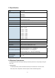
1.3 Specification Model WAP-7000 Standard support IEEE802.11a IEEE802.3 IEEE802.3u Interface Wireless IEEE802.
2. Environmental factors The wireless network is easily affected by many environmental factors. Every environment is unique with different obstacles, construction materials, weather, etc. It is hard to determine the exact operating range of WAP-7000 in a specific location without testing. 3. Antenna adjustment Please check the specification of the antenna you want to use, and make sure it can be used on WAP-7000.
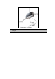
Chapter 2 Hardware Installation Before you proceed with the installation, it is necessary that you have enough information about the WAP-7000. 1. Locate an optimum location for the WAP-7000. 2. Assemble the 5GHz antenna to WAP-7000. Try to place them to a position that can best cover your wireless network. The antenna’s position will enhance the receiving sensitivity.
Note: ONLY use the power adapter supplied with the WAP-7000. Otherwise, the product may be damaged.
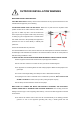
OUTDOOR INSTALLATION WARNING ! IMPORTANT SAFETY PRECAUTIONS: LIVES MAY BE AT RISK! Carefully observe these instructions and any special instructions that are included with the equipment you are installing. CONTACTING POWER LINES CAN BE LETHAL. Make sure no power lines are anywhere where possible contact can be made. Antennas, masts, towers, guy wires or cables may lean or fall and contact these limes.
corrosion-resistant connectors. Refer to the National Electrical Code for grounding details. IF A PERSON COMES IN CONTACT WITH ELECTRICAL POWER, AND CANNOT MOVE: DON’T TOUCH THAT PERSON, OR YOU MAY BE ELECTROCUTED. Use a non-conductive dry board, stick or rope to push or drag them so they no longer are in contact with electrical power. Once they are no longer contacting electrical power, administer CPR if you are certified, and make sure that emergency medical aid has been requested.
Chapter 3 IP Discover Utility A simple Windows utility is supplied on the CD-ROM. This utility can be used to locate the IP address of the WAP-7000 on the same network segment. Although the WAP-7000 has a default IP address, this utility is useful when the network administrator forgets the modified IP address. Before using this utility, please make sure the personal firewall installed in your PC is disabled. Below are the installation and usage procedures: 1.
Chapter 4 Web Configuration Web configuration provides a user-friendly graphical user interface (web pages) to manage your WAP-7000. The WAP-7000 with an assigned IP address (e.g.http://192.168.1.20) allows you to monitor and configure via web browser (e.g., MS Internet Explorer or Netscape). 1. Open your web browser. 2. Enter the IP address of your WAP-7000 in the address field (default IP address is http://192.168.1.20).
Type Password Again Re-type the new password again. SSH Server Enable or disable the built-in SSH server. SSH is a secured telnet-like mechanism to invoke the command line interface. All the commands and response will be encrypted. The SSH port is 22. You need to have an SSH client to access SSH server. SNMP Community Enter the community string, usually either "Public" or "Private". Trap Receiver Trap is the notification of certain events generated by SNMP agent to send to a network management server.
Manually setup IP address If selected, the following data must be entered. IP Address - The IP Address of this device. Enter an unused IP address from the address range on your LAN. Subnet Mask - The Network Mask associated with the IP Address above. Enter the value used by other devices on your LAN. Default Gateway - The IP Address of your Gateway or Router. Enter the value used by other devices on your LAN.
Bridge Type There are two options selectable: Master Bridge and Slave Bridge. For a Point-to-MultiPoint installation, there must be a Master Bridge device which located at the Hub station to host the wireless connections with the remote Slave Bridges. Please refer to the illustration below. One Master Bridge supports at most four Slave Bridges. For a Point-to-Point installation, please configure both devices in Slave Bridge mode.
Data Rate (Mbps) Rates of 6, 9, 12, 18, 24, 36, 48 and 54Mbps are supported for the wireless mode of 54Mbps (802.11a). And, rates of 12, 18, 24, 36, 48, 72, and 108Mbps are supported for the wireless mode of 108Mbps (802.11a Turbo). The mode of 108Mbps offers the double data rate than of 54Mbps. In order to maximize the system performance, it is recommended to follow the following suggestions.
Super Bridge Mode Super Bridge Mode provides three mechanisms to improve the bridge throughput. Compression: Frame is compressed by hardware before transmitting. Note that the compression may save bandwidth but would consume frame process time. In case of the data is already compressed (eg. mpeg frame), please do NOT turn on this function. Bursting: Turning on Bursting function enables multiple frames are transmitted at SIFS intervals, which may reduce transmission overhead.
Master / Slave Bridge Security Enable or Disable the security mechanism. Entry Method Hexadecimal: The key input must be hexadecimal (0-9, A-F). ASCII: The key input can be any character. The Entry Method of both Master and Slave Bridges must be identical. Encryption Type WAP-7000 supports three encryption types: 64-bit / 128-bit / 152-bit WEP. The Encryption Type of both Master and Slave Bridges must be identical.
Unique Key (Master Bridge only) In some special applications, you may need to assign different key for each Master-Slave link instead of the same key for all links. It can be done by setting up a Unique Key for each Slave Bridge. The MAC addresses of the Slave Bridge will be shown in the Bridge MAC field. Please input the key value for corresponding Slave Bridge in the Key field. The key value must be complied with the encryption type as well.
Values on this page are automatically refreshed every one-minute. You may manually click the refresh button of browser to get the most updated data more frequent. As RF signal strength is more critical for outdoor deployment purpose, RSSI bar is refreshed every 2 seconds. Due to frequent refresh of Statistics page, it is strongly recommended that you close this page when performing network performance tests. Encryption Displays current state of encryption; the value is Yes or No.
Error Frame Displays the error count for both receive and transmission. Signal Strength (RSSI) Display the strength of the receive and transmit signals in dBm. Refresh every 2 seconds. Data Rate Displays the receive and transmit data rate in Mbps. Receive Errors Displays the number of receive errors. Discarded Frame Displays the number of receive discarded frames. Duplicate Frame Displays the number of receive duplicate frames. CRC Error Displays the number of receive CRC errors.
Discarded Frame Displays the number of transmit discarded frames. Excessive Retry Frame Displays the number of transmit excessive retries. 4.5 File Upload This screen allows you to upgrade your WAP-7000 when new firmware is released. To perform the Firmware Upgrade: 1. Click the “Browse” button and navigate to the location of the upgrade file. 2. Select the upgrade file. Its name will appear in the Upgrade File field. 3. Click the “Upload & Update” button to commence the firmware upgrade.
4.6 System Info This screen lists the important system information and software / hardware inventory data. System Uptime The operating time since the WAP-7000 was booted up. Ethernet / 5GHz Bridge MAC The MAC addresses of the Ethernet and wireless interfaces. Capability It is fixed as Bridge for WAP-7000. Model Display the model name of this WAP-7000. Serial Number Display the serial number of this WAP-7000. Hardware / Software Version Display the version of hardware and software.
4.7 Reboot When all the parameters have been setup according to the network configuration and requirements, click “Update” and “Reboot“ for parameter changes taking effect. When starting reboot, system will prompt you a rebooting window. It takes at least 30 seconds to finish the reboot process.
Chapter 5 WLAN Planning 5.1 Site Survey The following operating and environmental conditions must be considered when performing a site survey: Data rates – The sensitivity and the radio range are inversely proportional to data rates. Therefore, the maximum radio range is achieved at the lowest workable data rate, and a decrease in receiver threshold sensitivity occurs as the radio data rate increases. Antenna type and placement – Proper antenna configuration is a critical factor in maximizing radio range.
If there is any obstacle in the radio path, it may still be a radio link but the quality and the signal strength will be affected. Ensuring the maximum clearance from objects on a path is important to locate the antennas and the height. For the long-distance links, the radio signals might be lost partially due to the non-LOS issue. As we setup the radio path for the wireless bridge link, it needs to consider these factors: Avoid any partial line-of-sight between the antennas.
2 mile (3.2 km) 12.7 ft (3.9 m) 1 ft (0.3 m) 13.7 ft (4.2 m) 3 mile (4.8 km) 15.6 ft (4.8 m) 2 ft (0.6 m) 17.6 ft (5.4 m) 4 mile (6.4 km) 18 ft (5.5 m) 3 ft (0.9 m) 21 ft (6.4 m) 5 mile (8 km) 20 ft (6.1 m) 4 ft (1.2 m) 24 ft (7.3 m) 7 mile (11.3 km) 24 ft (7.3 m) 8 ft (2.4 m) 32 ft (9.7 m) 9 mile (14.5 km) 27 ft (8.2 m) 14 ft (4.3 m) 41 ft (12.5 m) 12 mile (19.3 km) 31 ft (9.5 m) 24 ft (7.3 m) 55 ft (16.
Chapter 6 Troubleshooting This chapter provides solutions to problems usually encountered during the installation and operation of the WAP-7000. The bridges can’t successfully associate with each other: To make sure the cables is connected properly. To check the POE adapter’s LED is on or not. To check the both Frequency settings are on the same channel or not. To check the data rate is matched with one and another through the statistic RSSI display or the advance setting inside the Frequency setting.