0/100/1000Mbps Intelligent Gigabit / Fast Ethernet Switch WGSD-1020 User’s Manual
Trademarks Copyright PLANET Technology Corp. 2003. Contents subject to revision without prior notice. PLANET is a registered trademark of PLANET Technology Corp. All other trademarks belong to their respective owners. Disclaimer PLANET Technology does not warrant that the hardware will work properly in all environments and applications, and makes no warranty and representation, either implied or expressed, with respect to the quality, performance, merchantability, or fitness for a particular purpose.
TABLE OF CONTENTS 1. INTRODUCTION ....................................................................................................................................... 1 1.1 CHECKLIST .............................................................................................................................................. 1 1.2 ABOUT THE SWITCH................................................................................................................................. 1 1.3 FEATURES.................
APPENDIX A NETWORKING CONNECTION............................................................................................. 86 A.1 SWITCH‘S RJ-45 PIN ASSIGNMENTS ...................................................................................................... 86 A.2 10/100MBPS, 10/100BASE-TX ............................................................................................................. 86 A.3 RJ-45 CABLE PIN ASSIGNMENT ....................................................................
1. INTRODUCTION 1.1 Checklist Check the contents of your package for following parts: ● WGSD-1020 ● User's manual CD ● RS-232 cable ● Power cord ● Quick installation Guide If any of these pieces are missing or damaged, please contact your dealer immediately, if possible, retain the carton including the original packing material, and use them against to repack the product in case there is a need to return it to us for repair. 1.
◆ Support IGMP V1.0 ◆ Support LACP IEEE 802.3ad Port Trunking ◆ Support MAC address filtering ◆ Complies with IEEE 802.
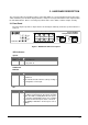
2. HARDWARE DESCRIPTION This section describes the hardware features of the Giga Switch. For easier management and control of the switch, familiarize yourself with its display indicators, and ports. Front panel illustrations in this chapter display the unit LED indicators. Before connecting any network device to the Switch, read this chapter carefully. 2.1 Front Panel The unit front panel provides a simple interface monitoring the switching. It includes a power indicator for each port.
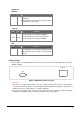
1000Base-T LNK/ACT LED Color Function LNK / ACT Green Lit: indicate the link through that port is successfully established. Blink: indicate that the switch is actively sending or receiving data over that port. 1000/100 LED Color Function 1000 Orange Lit: indicate that connection made through the corresponding port is running at 1000Mbps. 100 Green Lit: indicate that connection made through the corresponding port is running at 100Mbps.
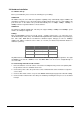
2.3 Hardware Installation 2.3.1 Before start up Before your installation, please refer to the followings for your cabling: 100Base-TX All 100Base-TX ports come with auto-negotiation capability. They automatically support 100Base-TX and 10Base-T networks. Users only need to plug a working network device into one of the 100Base-TX ports, then turn on the Switch. The port will automatically runs in 10Mbps, 20Mbps, 100Mbps or 200Mbps after the negotiation with the connected device.
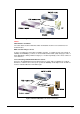
Figure 3. End node or Hub or Switch connection Notice: Cable distance for Switch The cable distance between Ethernet Switch and hub/PC should not exceed 100 meter for UTP/STP cable. Make sure the wiring is correct It can be used Category 3/4/5 cable in 10 Mbps operation. To reliably operate your network at 100Mbps and 1000Mbps, you must use an Unshielded Twisted-Pair (UTP) Category 5 cable, or better Data Grade cabling. While a Category 3 or 4 cable may initially seem to work, it will soon cause data loss.
3. SWITCH MANAGEMENT This chapter describes how to manage the Switch. Topics include: - Overview - Management methods - Assigning an IP address to the Switch - Logging on to the Switch 3.1 Overview The Switch provides a user-friendly, menu driven console interface.
3.2.2 Remote Console Management You can manage the Switch remotely by having a remote host establish a Telnet connection to the Switch via an Ethernet or modem link. Using this management method: The Switch must have an Internet Protocol (IP) address The Remote Console Management interface is identical in appearance and functionality to the Local Console Management interface described in the previous section. 3.2.
4. CONSOLE INTERFACE 4.1 CONNECT TO PC RS-232 serial cable Use the bundled RS-232 serial cable and attach the 9-pin female connector to the male connector on the switch. Plug the other side of this cable to your PC. Hyper Terminal In Windows 95/98/2000/XP, launch “HyperTerminal”, create a new connection, and adjust settings as below: § Emulation: VT-100 compatible § Baud per second: 9600 § Data bits: 8 § Parity: None § Stop bits: 1 § Flow Control: None To gain a demo, please see the Figure 4-1.
4.2 Login in Login is required to access the command console after the self-test completes successfully. The factory default user name is "admin" without password. You may change it in the System Menu. To access to the Main Menu, please always enter the correct user name. (See Figure 4-2) Figure 4-2 WGSD-1020 login screen 4.3 Main screen After login the WGSD-1020, the main screen shows as below.
4.3.1 Status and Counters From the Switch main menu screen (see Figure 4-3), highlight Status and counters and press enter. The Status and Counters sub-screen in Figure 4-4 appears. Figure 4-4 Status and Counters sub-screen This sub-menu contains four items: Port Status: Please refer to chapter 4.3.1.1. Port Counters: Please refer to chapter 4.3.1.2 System Information: Please refer to chapter 4.3.1.3 Main Menu: return to main menu. 4.3.1.1 Port Status Display the status of each port on WGSD-1020.
4.3.1.2 Port Counters Display the traffic counters of each port on WGSD-1020. Figure 4-6 Port Counters screen 4.3.1.3 System Information Display the Switch information.
4.3.2 Switch Static Configuration From the Switch Static Configuration screen (see Figure 4-8), highlight Switch Static Configuration and press Enter. The Switch Static Configuration sub-screen in Figure 4-9 appears. Figure 4-8 Switch Static Configuration screen Figure 4-9 Switch Static Configuration sub-screen This sub-menu contains eight items: Administration Configuration: please refer to chapter 4.3.2.1. Port & Trunking Configuration: please refer to chapter 4.3.2.2.
4.3.2.1 Administration Configuration Figure 4-10 Device Configuration screen This sub-menu contains five items: Device Information: please refer to chapter 4.3.2.1.1 IP Configuration: please refer to chapter 4.3.2.1.2 Change Username: please refer to chapter 4.3.2.1.3 Change Password: please refer to chapter 4.3.2.1.4 Previous Menu: return to previous menu 4.3.2.1.1 Device Information Display the Device information.
4.3.2.1.2 IP Configuration Press ”Edit” to modify the IP address, Subnet Mask and Gateway. Figure 4-12 IP Configuration screen Press “Tab” to move the cursor to IP Address, Subnet Mask and Gateway to input new value. After setup completed, press “ctrl-A” to save the current configuration. The following screen in Figure 4-13 appears. Figure 4-13 IP Configuration save successful screen You need to reboot the Switch to take effect of your IP configuration.
4.3.2.1.3 Change Username Press “Edit” to input the new username and choose “save” to save the current configuration. The following screen in Figure 4-14 appears.
4.3.2.1.4 Change Password Allow user to modify the password. Figure 4-16 Password Configuration screen Modify the password procedure: 1. Enter old password: empty (Default is no password) 2. Enter new password: * * * ( New password 123) 3. Enter again : * * * ( New password 123) 4. Press “Enter” to apply the new password.
4.3.2.2 Port & Trunking Configuration From the Switch Static Configuration sub-screen (see Figure 4-9), highlight Port Trunk Configuration and press enter. The Port Trunk Configuration screen in Figure 4-17 appears. Figure 4-17 Port & Trunking Configuration screen Press ” Edit” to configure the trunk group. After setup completed, press “ctrl-A” to save the current configuration. The following screen in Figure 4-18 and 4-19 appears.
Figure 4-19 Port & Trunking Configuration save successfully screen 4.3.2.3 Port Sniffer Configuration From the Switch Static Configuration sub-screen (see Figure 4-9), highlight Port Sniffer Configuration and press enter. The Port Sniffer Configuration screen in Figure 4-20 appears. Figure 4-20 Port Sniffer Configuration screen Press ”Edit” to configure the Port Sniffer function. Roving Analysis: provide disable or enable port sniffer function.
4.3.2.4 VLAN Configuration From the Switch Static Configuration sub-screen (see Figure 4-9), highlight VLAN Configuration and press enter. The VLAN Configuration screen in Figure 4-21 appears. Figure 4-21 VLAN Configuration screen This sub-menu contains four items: VLAN Configure: please refer to chapter 4.3.2.4.1 Create a VLAN Group: please refer to chapter 4.3.2.4.2 Edit/ Delete a VLAN Group: please refer to chapter 4.3.2.4.3 Previous Menu: return to previous menu 4.3.2.4.
. Figure 4-23 IEEE 802.1Q VLAN Configuration screen Press space bar switch to 802.1Q with GVRP in VLAN mode. The screen in Figure4-24 appears. Figure 4-24 IEEE 802.1Q VLAN with GVRP screen Press space bar switch to Port-based VLAN in VLAN mode. The screen in Figure4-25 appears.
Figure 4-25 Port-based VLAN screen 4.3.2.4.2 Create a VLAN Group To add a VLAN group, the VLAN ID range is 1-4094. Figure 4-26 Add a VLAN Group screen Add a VLAN Group procedure: 1. Press “ Edit” to input the VLAN name and VLAN ID. 2. Choose different VLAN protocol through the space bar. 3. Under 802.1Q and 802.1Q VLAN mode. Set Tagged, Untagged or no (not belong to any VLAN group) of each port. 4. Under Port-based VLAN mode. Set Member or no (not belong to any VLAN group) of each port. 5.
4.3.2.4.3 Edit / Delete VLAN Group Allow editing and deleting VLAN GROUP. Figure 4-27 Edit a VLAN Group screen 4.3.2.5 Priority Configuration Displays the options available for assigning High and Low priority to each port. From the Switch Static Configuration sub-screen (see Figure 4-9), highlight Priority Configuration and press enter. The Priority Configuration screen in Figure 4-28 appears Figure 4-28 Priority Configuration screen Press ” Edit” to assigning High or Low priority of each port.
Figure 4-29 Priority Configuration save successfully screen Press any key return to the previous menu. 4.3.2.6 MAC Address Configuration Provide static MAC address and Filtering MAC address and previous Menu. From the Switch Static Configuration sub-screen (see Figure 4-9), highlight MAC address Configuration and press enter. The MAC address Configuration screen in Figure 4-30 appears. Figure 4-30 MAC Address Configuration screen This sub-menu contains 3 items.
4.3.2.6.1 Static MAC Address Figure 4-31 Static MAC Address Configuration screen Press, “Add” to add a static MAC address, after setup completed, press “Ctrl-A” and choose “Save” to save the current configuration. The screen in Figure 4-32 appears Figure 4-32 Static MAC Address Configuration screen Press any key return to the previous menu.
4.3.2.6.2 Filtering MAC Address Figure 4-33 Filter MAC Address Configuration screen Press “Add” to add a Filter MAC address, after setup completed, press “Ctrl-A” and choose “Save” to save the current configuration.
4.3.2.7 Misc Configuration From the Switch Static Configuration sub-screen (see Figure 4-9), highlight Misc Configuration and press enter. The Misc Configuration sub-screen in Figure 4-35 appears. Figure 4-35 Misc Configuration screen This sub-menu contains five items: Port Security: please refer to chapter 3.3.2.7.1 MAC Age Interval: please refer to chapter 3.3.2.7.2 Broadcast Storm Filtering: please refer to chapter 3.3.2.7.3 Max bridge transmits delay bound: please refer to chapter 3.3.2.7.
4.3.2.7.2 MAC Age Interval Allow to setting the aging time of WGSD-1020. The maximum value is 765 sec. Figure 4-37 Aging Time Configuration screen Press “Edit” to input the aging time value and press enter to choose the “save” for save the current configuration. The screen in Figure 4-38 appears. Figure 4-38 Aging time Configuration save successfully screen Press any key for return to the previous menu.
4.3.2.7.3 Broadcast Storm Filtering Provide disable and 5, 10, 15, 20 or 25 Broadcast storm filter mode. Figure 4-39 Broadcast storm filter screen Broadcast Storm Filter setup procedure: 1. Press “Edit” to input 5, 10, 15, 20 or 25 broadcast storm filter. 2. After setup completed, press” Ctrl-A” to “Action menu” and choose “save” to save the current configure. The screen in Figure 4-40 appears. 3. Press any key for return to the previous menu. 4.3.2.7.
4.3.2.7.4.1 Max bridge transmit delay bound Provide “OFF” and 1, 2, or 4 sec. for selection. Figure 4-41 Max Bridge transmit delay bound screen Setup procedure: 1. Press “Edit” to input OFF and 1, 2 or 4 sec. 2. After setup completed, press” Ctrl-A” to “Action menu” and choose “save” to save the current configure. The screen in Figure 4-42 appears. Figure 4-42 Max Bridge transmit delay bound save successfully screen 3. Press any key for return to the previous menu.
4.3.2.7.4.2 Enable Delay Bound Provide disable or enable Delay Bound function. Figure 4-43 Enable Delay Bound screen Setup procedure: 1. Choose disable or enable through the space bar. 2. After setup completed, press” Ctrl-A” to “Action menu” and choose “save” to save the current configure. The screen in Figure 4-44 appears. Figure 4-44 Enable Delay Bound save successfully screen 3. Press any key for return to the previous menu.
4.3.2.7.4.3 Max Delay Time Allow inputting the Max Delay Time. Figure 4-45 Max Delay Time screen Setup procedure: 1. Press “ Edit” to input the Max Delay Time value. 2. After setup completed, press” Ctrl-A” to “Action menu” and choose “save” to save the current configure. The screen in Figure 4-46 appears. Figure 4-46 Max Delay Time save successfully screen 3. Press any key for return to the previous menu. 4.3.2.8 Main Menu Return to the main menu.
4.3.3 Protocol Related Configuration From the Switch main menu screen (see Figure 4-3), highlight Protocol Related Configuration and press enter. The Status and Counters screen in Figure 4-47 appears. Figure 4-47 The Protocol Related Configuration screen This subnet menu contains five items: STP: please refer to chapter 4.3.3.1. SNMP: please refer to chapter 4.3.3.2. GVRP: provide disable or enable GVRP function. LACP: provide LACP configuration. Previous Menu: return to Main menu. 4.3.3.
This sub-menu contains four items: STP Enable: please refer to chapter 4.3.3.1.1 System Configuration: please refer to chapter 4.3.3.1.2 Per port Configuration: please refer to chapter 4.3.3.1.3 Previous Menu: return to previous menu. 4.3.3.1.1 STP Enable Provide disable or enable STP function Figure 4-49 STP enable /disable screen Setup procedure: 1. Press “ Edit” to disable or enable STP function. 2. After setup completed, press” Ctrl-A” to “Action menu” and choose “save” to save the current configure.
4.3.3.1.2 System Configuration Allow modify the STP system configuration. Figure 4-51 STP system configuration screen Setup procedure: 1. Press “ Edit” to modify the Spanning Tree Parameters. 2. After modify completed, press” Ctrl-A” to “Action menu” and choose “save” to save the current configure. The screen in Figure 4-52 appears. Figure 4-52 STP system configuration save successfully screen 3. Press any key for return to the previous menu.
4.3.3.1.3 Per Port Configuration Allow edit per port STP configuration. Figure 4-53 STP Port configuration screen Setup procedure: 1. Press “ Edit” to modify the path cost and priority of each port. 2. After setup completed, press” Ctrl-A” to “Action menu” and choose “save” to save the current configure. The screen in Figure 4-54 appears. Figure 4-54 STP Port configuration screen 3. Press any key for return to the previous menu.
4.3.3.2 SNMP Provide SNMP configuration. Figure 4-55 SNMP configuration screen This subnet menu contains four items: 1. System Options: please refer to chapter 4.3.3.2.1 2. Community Strings: please refer to chapter 4.3.3.2.2 3. Trap Managers: please refer to chapter 4.3.3.2.3 4. Previous Menu: please refer to chapter 4.3.3.2.4 4.3.3.2.1 System Options Allow inputting the system name, system location, system contact.
Setup procedure: 1. Press “ Edit” to input the system name, system contact, system location. 2. After setup completed, press” Ctrl-A” to “Action menu” and choose “save” to save the current configure. The screen in Figure 4-57 appears. Figure 4-57 System Options configuration save successfully screen 3. Press any key for return to the previous menu. 4.3.3.2.2 Community Strings Allow adding SNMP community name. Figure 4-58 SNMP Community configuration screen Setup procedure: 1.
Figure 4-59 Add SNMP Community name save successfully screen 3. Press any key for return to the previous menu. 4.3.3.2.3 Trap Managers Allow adding Trap Managers. Figure 4-60 Add SNMP Community name screen Setup procedure: 1. Press “Add” to enter into “Trap Managers” screen, then press “Edit” for input IP address and Community name. 2. After setup completed, press” Ctrl-A” to “Action menu” and choose “save” to save the current configure. The screen in Figure 4-61 appears.
Figure 4-61 Add Trap managers screen 3. Press any key for return to the previous menu. 4.3.3.2.4 Previous Menu Return to the previous menu. 4.3.3.3 GVRP Provide disable or enable GVRP function Figure 4-62 GVRP screen Setup procedure: 1. Press “Edit” to disable or enable the GVRP function. 2. After setup completed, press” Ctrl-A” to “Action menu” and choose “save” to save the current configure. The screen in Figure 4-63 appears.
Figure 4-63 GVRP save successfully screen 3. Press any key for return to the previous menu. 4.3.3.4 LACP Figure 4-64 LACP Configuration screen This subnet menu contains four items: 1. Aggregator Settings: please refer to chapter 4.3.3.4.1. 2. State Activity: please refer to chapter 4.3.3.4.2 3. LACP Status: please refer to chapter 4.3.3.4.3 4. Previous Menu: please refer to chapter 4.3.3.4.
4.3.3.4.1 Aggregator Settings Allow editing the LACP Group configuration. Figure 4-65 Aggregator settings screen 4.3.3.4.2 State Activity Allow to set LACP port state activity of each port. Figure 4-66 LACP port state Active configuration screen Setup procedure: 1. Press “Edit” for “passive” or “Active” selection of each port. 2. After setup completed, press” Ctrl-A” to “Action menu” and choose “save” to save the current configure. The screen in Figure 4-67 appears.
Figure 4-67 LACP port state Active configuration screen 3. Press any key for return to the previous menu. 4.3.3.4.3 LACP Status Display the LACP groups status. Figure 4-68 LACP Group Status screen 4.3.3.4.4 Previous Menu Return to the previous menu. 4.3.3.5 Main Menu Return to the main menu.
4.3.4 Reboot Switch Provide reboot the Switch and reset to switch to default mode. Figure 4-69 Reboot Switch screen This subnet menu contains three items: 1. Default: please refer to chapter 4.3.4.1. 2. Restart: please refer to chapter 4.3.4.2. 3. Previous Menu: refer to chapter 4.3.4.3 4.3.4.1 Default Reset the Switch to the factory default mode. The screen in Figure 4-70 appears. Figure 4-70 Reset Switch screen Press “Y” for reboots the switch to default mode.
Figure 4-71 Resetting Switch screen 4.3.4.2 Restart Provide restart the Switch. The screen in Figure 4-72 appears. Figure 4-72 Restart Switch screen 4.3.4.3 Previous Menu Return to the main menu.
4.3.5 Command Line Provide system command for WGSD-1020. The screen in Figure 4-73 appears. Figure 4-73 Command line screen Type “Help” command for helps parameters. The screen in Figure 4-74 appears. Figure 4-74 Help parameters screen 4.3.6 Logout Provide logout the Switch.
5. WEB MANAGEMENT Before login the Web interface of WGSD-1020, please setup the “IP Address” with local serial console port( RS232 port) and use this IP address to configure WGSD-1020 through the Telnet and Web interface. Or modify your PC’s IP domain to the same with WGSD-1020 then use the default IP address to remote configure WGSD-1020 through the Telnet and Web interface. 5.1 Login in to the Switch To access the Web-browser interface you must first enter the user name.
5.2 Port Status This section provides detail status of each port from WGSD-1020. Figure 5-3 WGSD-1020 Port Status Web Page screen State: display the link state of each port on WGSD-1020. Link Status: the state of the link test, indicating a valid link partner device. "Up" means a device is successful connected to the port. “Down” means no device is connected. Auto-Negotiation: auto-negotiation state of each port on WGSD-1020. Speed Status: display the speed state of each port on WGSD-1020.
5-3 Port Statistics For those selected port, this function could provide you with an individual statistical counter. It is a useful page for administrator to monitor each port’s usage condition. Also, it is helpful to troubleshooting network problems. Please note that the updating rate is defined in System Configuration menu.
5-4 Administrator This section contains management function on WGSD-1020. Figure 5-5 WGSD-1020 Administrator Web Page screen This management function is shown as below: IP Address: please refer to section 5.4.1 Switch Settings: please refer to section 5.4.2 Console Port Information: please refer to section 5.4.3 Port Controls: please refer to section 5.4.4 Trunking: please refer to section 5.4.5 Filter Database: please refer to section 5.4.6 VLAN Configuration: please refer to section 5.4.
5.4.1 IP Address This section allows modify the IP address, Subnet Mask, Gateway of WGSD-1020. Figure 5-6 WGSD-1020 modify IP Address Web Page screen After modifying the new IP address, Subnet Mask, Gateway, please click “Apply” button then the following screen in Figure 5-7 appears. Click “Reboot” button. WGSD-1020 will reboot to take effect for the new IP address, Subnet Mask, Gateway.
You can click” Help” button; the IP Address Overview screen in Figure 5-8 appears. Figure 5-8 WGSD-1020 IP Address Overview Web Page screen Click “Close” to close this screen.
5.4.2 Switch Settings This section provide Switch basic information and allow modify the Switch settings Figure 5-9 WGSD-1020 Switch Basic Settings Web Page screen 5.4.2.1 Basic: Description: display the Switch system name. MAC address: display the Switch MAC Address. Firmware version: display the Switch current firmware version. Hardware version: display the Switch current hardware version. Default config value version: display the default eeprom version.
Figure 5-10 WGSD-1020 Switch Advanced Settings Web Page screen 5.4.2.2 Advanced: Enter the settings, then click Submit to apply the changes on this page. MAC Table Address Entry Age-Out Time: type the number of seconds that an inactive MAC address remains in the Switch’s address table. The valid range is 300-765 seconds. The default value is 300 sec. Max bridge transmit delay bound control: limit the packets queuing time in switch, if enable this function, the packets queued exceed will be drop.
Port-based VLAN mode Note: Make sure of “Max bridge transit delay bound control” is enabled before enabling delay bound, because enable delay bound must work under “ Max bridge transit delay bound control” is enabled. You can click “Help” button; the following screen in Figure 5-11 appears. Figure 5-11 WGSD-1020 Configuring the Switch Web Page screen Click “Close” to close this screen.
5.4.3 Console Port Information Display the WGSD-1020 console port information. Figure 5-12 WGSD-1020 Console Information Web Page screen You can click “Help” button; the following screen in Figure 5-13 appears. Figure 5-13 WGSD-1020 Console Setting Help Web Page screen Click “Close” to close this screen.
5.4.4 Port Controls This section introduces detail settings of per port on WGSD-1020. Figure 5-14 WGSD-1020 Port Controls Web Page screen State: provide disable or enable any port of WGSD-1020. Auto-Negotiation: allow disable or enable Auto-negotiation of any port on WGSD-1020. Speed: allow set various speed mode of any port on WGSD-1020. Duplex: allow to set half or full duplex mode of any port on WGSD-1020. Flow Control: provide disable or enable flow control function.
5.4.5 Trunking This section displays the screen for trunking a group of ports together to speed up data transmission. Figure 5-15 WGSD-1020 Trunking Web Page screen 5.4.5.1 Aggregator Setting parameters: System Priority: A value used to identify the active LACP. The Switch with lowest value has the highest priority and is selected as the active LACP. Group ID: After creating a new link aggregation across two or more ports, choose the “Group ID” and click “Get”.
Figure 5-16 WGSD-1020 Trunk Help Web Page screen Click “Close” to close this screen. 5.4.5.2 Port aggregator status: Provide the Port Aggregator information.
Actor: oneself device. Partner: link partner device. Admin: Switch default value. Oper: user setting and aggregating result. Priority: System priority value. MAC Address: Switch’s MAC Address. Key: aggregating key: 100 serial is LACP static trunking. 60000 serial is LACP dynamic trunking. I.e:101: 100MB group 1’s LACP static trunking, 102:100MB Group 2’s LACP static trunking. 60010: 10MB LACP dynamic trunking. Port Priority: always is 1. Port State: Active: ON: active status. OFF: passive status.
5.4.5.3 State Activity Allow setting the LACP State Activity of each port. Figure 5-18 WGSD-1020 State Activity Web Page screen Please check the detail description of parameters as below: Active( enable ): the port automatically sends LACP protocol packets. Passive ( not enable Active): the port does not automatically sends LACP protocol packets and only respond when it receives LACP protocol packets from the opposite device.
5.4.6 Filter Database Figure 5-20 WGSD-1020 IGMP Snooping Web Page screen Please check the detail description of parameters as below: IGMP Snooping: WGSD-1020 support IP multicast and allow enable IGMP protocol on Switch setting advanced page from the web interface. This web page provide IGMP Snooping information, you can see different multicast group, VID and member port. Please note the IP multicast address range is from 224.0.0.0 to 239.255.255.255.
Static MAC Address: when add a static MAC Address, it remains in the Switch’s address table, regardless of whether the device is physically connected to the Switch. This function make the Switch can relearn device’s MAC Address when the device is disconnected or power-off and active in the network again. The configure procedure is shown as below: 1. To add static MAC Address. 2. From the main menu, click “administrator” then click “Filter Database”. 3. Click “static MAC Address”. In the MAC address box.
Figure 5-23 WGSD-1020 Port Security Web Page screen Port Security: any port in security mode will be “locked” without permission of MAC address learning. Only the incoming packets with MAC already existing in the MAC address table can be forwarded normally. You can disable the port from learning any new MAC addresses then use the static MAC addresses screen to define a list of MAC address that can use the secure port. Enter the settings then click submit to apply the change on this web page.
Figure 5-25 WGSD-1020 MAC Filtering Web Page screen MAC Filtering: MAC address filtering allows the WGSD-1020 to drop unwanted traffic. Traffic is filtered based on the destination addresses. For example: if your network is congested because of high utilization from one MAC address, you can filter all traffic transmitted from that MAC address. You can click” Help” button; the following screen in Figure 5-26 appears.
5.4.7 VLAN Configuration A Virtual LAN ( VLAN) is a logical network grouping that limits the broadcast domain. It allows you to isolate network traffic so only members of the VLAN receive traffic from the same VLAN members. Basically, creating a VLAN from WGSD-1020 is logically equivalent of reconnecting a group of network device to another Layer 2 Switch. However, the entire network device is still plug into the same Switch physically. WGSD-1020 support port-based(refer to section 5.4.7.
+ Figure 5-28 WGSD-1020 Tag-based (IEEE 802.
5.4.7.2 Port VID In order for an end station send packets to different VLANs. Itself has to be either capable of tagging packets it sends with VLAN tags or attached to a VLAN-aware bridge that is capable of classifying and tagging the packet with different VLAN ID based on default PVID and other packet information. Figure 5-29 WGSD-1020 Port VID setting Web Page screen Please check the detail description of parameters as below: 1. From the main Tag-based (IEEE 802.1Q) VLAN page, click “Port VID Settings”.
5.4.7.3 Port Based VLAN Choose Port Based VLAN function operation Mode from Switch Settings. The following screen in Figure 5-30 appears. Figure 5-30 WGSD-1020 Port Based VLAN Web Page screen Create a new VLAN group and add member ports procedure: 1. Click “Add” to create a new VLAN group. The following screen in Figure 5-31 appears. 2. Type a name for the new VLAN and VLAN ID (between 1- 4094). 3. From the available ports box, select ports to add to the Switch and click “Add” 4.
Figure 5-31 WGSD-1020 Port Based VLAN setting Web Page screen Figure 5-32 WGSD-1020 Port Based VLAN setting successful Web Page screen - 70 -
5.4.8 Spanning Tree The Spanning Tree Protocol (STP) is a standardized method (IEEE 802.1D) for avoiding loops in Ethernet networks. When enable STP function, please ensure only one path at a time is active between any two nodes on the network. You can enable Spanning Tree Protocol from the Switch setting advanced item of web interface. We are recommended you to enable STP on whole Switches for ensures a single active path in the network.
You can view the spanning tree information about Root Bridge. The screen is shown as below: Figure 5-35 Root Bridge Information Web Page screen The following parameter can be configured of per port, after you setup completed. Please click “Apply” button to modify. Figure 5-36 Configure Spanning Tree Parameters of each port Web Page screen Please refer to Table 5-2 for per port Spanning Tree Parameters detail description. Parameter Description Port Priority Allow to set port priority of per port.
Figure 5-38 Spanning Tree Management Help Web Page screen Click “Close” to close this screen.
5.4.9 Port Sniffer The Port sniffer is a method for monitor traffic in WGSD-1020 networks. Traffic through ports can be monitored by one specific port. Traffic through the in or out monitored ports will be duplicated into sniffer port. Figure 5-39 WGSD-1020 Port Sniffer Web Page screen Please check the detail description of parameters as below: Roving Analysis: provide disable or enable port sniffer function.
5.4.10 SNMP Allow to management the WGSD-1020 through the Simple Network Management Protocol (SNMP) It provides protocol that governs the transfer of information between management stations (PC with SNMP software) and agent (switches). The management Information Base (MIB) is installed correctly on the management station. Figure 5-41 WGSD-1020 SNMP Management Web Page screen Use this page to define the management stations as trap managers and key in SNMP community strings.
Figure 5-43 Community Strings Web Page screen Please check the detail description of parameters as below: RO / Read Only: enables requests accompanied by this string to display MIB-object information. RW / Read Write: enables requests accompanied by this string to display MIB-object information and set MIB objects. Trap Manager A Trap manager is a management station that receives traps, the system alerts generated by the Switch. If Trap manager is not defined then there is no trap issued.
5.4.11 Security Manager Allow user to modify the User Name and Password of WGSD-1020. Figure 5-46 WGSD-1020 Security Manager Web Page screen 1. Input the new user name. 2. Input the new password. 3. Re-input the new password. 4. Click “Apply” button to modify.
5-5 TFTP Update Firmware The following menu options provide some system control functions to allow user to update latest firmware and remotely reboot WGSD-1020 system. Figure 5-47 WGSD-1020 TFTP Download New Image Web Page screen Firmware update requirements: 1. The latest firmware version of WGSD-1020. 2. WGSD-1020. 3. A TFTP server Firmware update procedure: 1. Install TFTP server in your PC. 2. Download the firmware file and put the file to the TFTP download directory. 3.
5-6 Configuration Backup This option allows you to backup the WGSD-1020’s configuration into a file. Figure 5-49 WGSD-1020 TFTP Configuration Web Page screen TFTP Restore Configuration: Figure 5-50 WGSD-1020 TFTP Restore Configuration Web Page screen Purpose: allow user restore the EEPROM value from this function. Usage: enter the TFTP Server IP Address and Backup File Name. Click “Apply” to restore EEPROM value.
TFTP Backup Configuration: Figure 5-51 WGSD-1020 TFTP Backup Configuration Web Page screen Purpose: allow user save the EEPROM value from this function. Usage: Enter the TFTP Server IP Address and Backup File Name. Click “Apply” to save current EEPROM value. You can click” Help” button; the following screen in Figure 5-48 appears. Click “Close” to close this screen.
5-7 Reset System This function provides reset the Switch to factory default mode.
5-8 Reboot System This function allows reboot the WGSD-1020. Figure 5-53 WGSD-1020 Reboot Switch Web Page screen You can click” Help” button; the following screen in Figure 5-54 appears. Figure 5-54 WGSD-1020 Reboot Switch Help Web Page Click “Close” to close this screen.
5-9 View the State, Link Activity and detail packet information To view the current state, link, and detail packet information for the WGSD-1020, click the RJ-45 jacks on the switch shown in your Browser’s screen. The LED Panel screen in Figure 5-55 appears.
6. SWITCH OPERATION 6.1 Address Table The Giga Switch is implemented with an address table. This address table composed of many entries. Each entry is used to store the address information of some node in network, including MAC address, port no, etc. This information comes from the learning process of Ethernet Switch. 6.2 Learning When one packet comes in from any port. The Giga Switch will record the source address, port no. and the other related information in address table.
7.TROUBLESHOOTING This chapter contains information to help you solve problems. If Giga Switch is not functioning properly, make sure the Ethernet Switch was set up according to instructions in this manual. The Link LED is not lit Solution: Check the cable connection and remove duplex mode of the Giga Switch Some stations can not talk to other stations located on the other port Solution: Please check the VLAN, port trunking and Port Sniffer function which may introduce this kind of problem..
APPENDIX A NETWORKING CONNECTION A.1 Switch‘s RJ-45 Pin Assignments 1000Mbps,1000Base T Contact MDI MDI-X 1 BI_DA+ BI_DB+ 2 BI_DA- BI_DB- 3 BI_DB+ BI_DA+ 4 BI_DC+ BI_DD+ 5 BI_DC- BI_DD- 6 BI_DB- BI_DA- 7 BI_DD+ BI_DC+ 8 BI_DD- BI_DC- Implicit implementation of the crossover function within a twisted-pair cable, or at a wiring panel, while not expressly forbidden, is beyond the scope of this standard. A.
Figure A-1: Straight-Through and Crossover Cable Please make sure your connected cables are with same pin assignment and color as above picture before deploying the cables into your network.
APPENDIX B TECHNICAL SPECIFICATIONS WGSD-1020 10/100/1000Mbps Intelligent Ethernet Switch Hardware Specification Ports Eight 10/ 100Base-TX , two 1000Base-T RJ-45 Auto-MDI/MDI-X ports Switch Fabric 5.6Gbps Switch Processing Scheme Store-and-forward Throughput (packet per second) 4.16Mpps Address Table 8K entries Queue Buffer 128Kbytes Flow Control Back pressure for half duplex, IEEE 802.
2080-000001-002