802.
Copyright Copyright © 2008 by PLANET Technology Corp. All rights reserved. No part of this publication may be reproduced, transmitted, transcribed, stored in a retrieval system, or translated into any language or computer language, in any form or by any means, electronic, mechanical, magnetic, optical, chemical, manual or otherwise, without the prior written permission of PLANET.
This device complies with Part 15 of the FCC Rules. Operation is subject to the Following two conditions: (1) This device may not cause harmful interference, and (2) this Device must accept any interference received, including interference that may cause undesired operation. Federal Communication Commission (FCC) Radiation Exposure Statement This equipment complies with FCC radiation exposure set forth for an uncontrolled environment.
TABLE OF CONTENTS CHAPTER 1 INTRODUCTION.................................................................................................. 1 1.1 PACKAGE CONTENTS .................................................................................................. 2 1.2 FEATURES .................................................................................................................. 3 1.3 SPECIFICATION ................................................................................................
7.6 STATISTICS ............................................................................................................... 87 CHAPTER 8 TOOLS .......................................................................................................... 88 8.1 CONFIGURATION TOOLS ............................................................................................ 89 8.2 FIRMWARE UPGRADE ................................................................................................ 90 8.
Chapter 1 Introduction Thank you for purchasing WNRT-620. This manual guides you on how to install and properly use the WNRT-620 in order to take full advantage of its features.
1.1 Package Contents Make sure that you have the following items: • • • • • One WNRT-620 One Power Adapter One CD Disk One Quick Installation Guide One Ethernet Cable Note: If any of the above items are missing, please contact your supplier for support.
1.2 Features z Compliant with IEEE 802.11n (Draft 2.0) wireless technology z Provides up to 300Mbps data rate z Support Wi-Fi Protected Setup (WPS) z Backward compatible with 802.11g / 802.11b standard z Farther coverage, less dead spaces and higher throughput with 802.11n technology z Supports 64/128-bit WEP, WPA (TKIP with IEEE 802.1x), WPA2 (AES with IEEE 802.
1.3 Specification Standard IEEE 802.11b/g, 802.11n Draft 2.0 Signal Type 11b mode: DSSS 11g mode: OFDM 11n mode: OFDM, MIMO Modulation 11b mode: CCK, DQPSK, DBPSK 11g mode: 64 QAM, 16 QAM, QPSK, BPSK 11n mode: 64 QAM, 16 QAM, QPSK, BPSK WAN Port 1 x 100Base-TX, Auto-MDI/MDI-X LAN Port 4 x 100Base-TX, Auto-MDI/MDI-X Antenna connector 3 x Fixed Omni Antenna Data Encryption 64 bit / 128 bit WEP, WPA-PSK, WPA, WPA2 Frequency 2.4GHz - 2.
Chapter 2 Hardware Installation Before you proceed with the installation, it is necessary that you have enough information about the WNRT-620.
2.1 Hardware Connection 1. Locate an optimum location for the WNRT-620. The best place for your WNRT-620 is usually at the center of your wireless network, with line of sight to all of your mobile stations. 2. Adjust the antennas of WNRT-620. Try to adjust them to a position that can best cover your wireless network. The antenna’s position will enhance the receiving sensitivity. 3. Connect RJ-45 cable to WNRT-620 LAN port.
-7-
2.
Chapter 3 Web Login Web configuration provides a user-friendly graphical user interface (web pages) to manage your WNRT-620. A WNRT-620 with an assigned IP address will allows you to monitor and configure via web browser (e.g., MS Internet Explorer or Netscape). 1. Open your web browser. 2. Enter the IP address of your WNRT-620 in the address field (default IP address is http://192.168.0.1). 3. A User Name and Password dialog box will appear. Please enter your User Name and Password here.
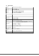
Section Description Select your Internet connection type and then input the configurations needed Quick Setup to connect to your Internet Service Provider (ISP). This section contains configurations for the Broadband router’s advance functions such as: Port Forwarding, Virtual Server, Access Control, Hacker General Setup Attack Prevention, DMZ, Special applications and other functions to meet your LAN requirements. You can also configure the wireless detail settings here.
Chapter 4 Quick Setup This section describes the basic configuration of the WNRT-620 and allows you to connect to Internet easily.
4.1 Time Zone The time information is used for Log entries and Firewall settings. You can keep the default Time Server address or set a new IP address for your router to synchronize its time. Click “Next” to continue. Parameter Description Select the time zone of the country you are currently in. The router will Set Time Zone set its time based on your selection. Remain it as default or, you can manually assign an IP address of the Time Server.
4.2 Broadband Type Before establishing the Internet connection, please be sure to check with your ISP, and obtain all necessary information from them. Broadband Description ISP will automatically give you an IP address. Please refer to section Cable Modem 4.2.1 for details. ISP has given you a fixed IP address already. Please refer to section Fixed-IP Xdsl 4.2.2 for details. ISP requires you to use a Point-to-Point Protocol over Ethernet (PPPoE) PPPoE xDSL connection. Please refer to section 4.2.
4.2.1 Cable Modem With Cable Modem connection, the ISP will automatically give you an IP address. Some ISP may also require you to fill in additional information such as Host Name and MAC address (see screen below). Note: The Host Name and MAC address section is optional and you can skip this section if your ISP does not require these settings for you to connect to the Internet. Parameters Description Host Name Type in the host name provided by your ISP if any; otherwise, just leave it blank.
4.2.2 Fixed-IP xDSL Select Fixed-IP xDSL if you’re ISP has given you a specified IP address. Your ISP should provide all the information required in this section. Parameters Description IP address assigned by your The IP address that you’re ISP should provide you. Service Provider Subnet Mask Enter the Subnet Mask provided by your ISP (e.g. 255.255.255.0). DNS Address The IP address of ISP’s DNS (Domain Name Service) Server. Service Provider Gateway The ISP’s IP address gateway.
4.2.3 PPPoE xDSL Select PPPoE if your ISP requires the PPPoE protocol for Internet connectivity. Your ISP should provide all the information like user name, password required in this section. Parameters Description User Name Enter the User Name provided by your ISP for the PPPoE connection. Password Enter the Password provided by your ISP for the PPPoE connection. Service Name This is an optional parameter. Leave it blank unless your ISP requires it. This is an optional parameter.
network application software, computer virus or hacker attacks from the Internet. For example, some software sends network packets to the Internet in the background, even when you are not using the Internet. So please turn off your computer when you are not using it. This function also may not work with some ISP. So please make sure this function can work properly, especially when your ISP charges you by time used.
explanation on MAC address). Use the following IP Select it if the ISP provides you a static IP to connect to the PPTP server. address This is the IP address that your ISP has given you to establish a PPTP IP Address connection. Subnet Mask Enter the Subnet Mask provided by your ISP (e.g. 255.255.255.0) Gateway Enter the IP address of the ISP’s Gateway. Enter the User Name provided by your ISP for the PPTP connection. User ID Sometimes called a Connection ID.
press “OK”, you will see a web screen to prompt you the configurations save successfully. Please refer to section 4.2.7 for the information of this screen. 4.2.5 L2TP xDSL Select L2TP if your ISP requires the L2TP protocol to connect to the Internet. Your ISP should provide all the information required in this section. Parameter Description Obtain an IP address Select it if the ISP requires you to obtain an IP address by DHCP automatically.
Subnet Mask Enter the Subnet Mask provided by your ISP (e.g. 255.255.255.0) Gateway Enter the IP address of the ISP’s Gateway. Enter the User Name provided by your ISP for the L2TP connection. User ID Sometimes called a Connection ID. Password Enter the Password provided by your ISP for the L2TP connection If your LAN has a L2TP gateway, enter that L2TP gateway’s IP address here. If L2TP Gateway you do not have a L2TP gateway, enter the ISP’s Gateway IP address above. This is an optional parameter.
4.2.6 Telstra Big Pond Select Telstra Big Pond if you are live in Australia and your ISP requires this protocol to connect to the Internet. Your ISP should provide all the information required in this section. Parameters Description User Name Enter the User Name provided by your ISP for the connection. Password Enter the Password provided by your ISP for the connection.
Please wait for 30 seconds for WNRT-620 restart. After restart procedure finished, please click “OK” to return to HOME screen.
Chapter 5 General Setup After click on the “General Setup” button at the main Page, you should see the screen below. The General Setup contains advanced features that allow you to configure the router to meet the network’s needs such as: Wireless, Port Forwarding, Virtual Server, Access Control, URL Blocking, Special Applications, DMZ and other functions.
5.1 System This section shows how to setup the Broadband router’s system Time Zone, Password and Remote Management Administrator. 5.1.1 Time Zone The Time Zone allows WNRT-620 to allocate its time on the settings configured here; it will affect log display functions such as Security Log and Firewall settings. Parameter Description Select the time zone of the country you are currently in. The router will set its time Set Time Zone based on your selection.
You can keep the default IP address or enter a new Time Server Address for this Time Server Address device to synchronize its time. You can also refer to the web site http://www.ntp.org to find a nearest time server. The router can also take Daylight savings into account. Select the check box to Daylight Savings enable your daylight saving configuration. You can set the days that you wish to start and stop daylight Savings Time. After the setup completed, please click “Apply” to save the settings.
5.1.3 Remote Management You can specify a Host IP address that can perform remote management from Internet. Parameters Description The IP address of the host on Internet that will have management / configuration access to the Broadband router. Leave it to 0.0.0.0 means anyone can access the router’s web-based configuration from any remote location. Click the Enabled box to enable the Remote Management function.
5.2 WAN The WAN Settings screen allows you to specify the type of Internet connection. The WAN settings offer the following selections for the router’s WAN port, Dynamic IP, Static IP, PPPoE, PPTP, L2TP, and Telstra Big Pond. Please select one of the connection types and click “More Configuration” button or select the option on the left window for configuration. 5.2.1 Dynamic IP If Dynamic IP is selected, your ISP will automatically give you an IP address.
5.2.2 Static IP If Static IP is selected, your ISP should provide all the information required in this screen. Please refer to the section 4.2.2 for more settings of this option. 5.2.3 PPPoE Select PPPoE if your ISP requires PPPoE protocol to connect to the Internet. Your ISP should provide all the information required in this section. Please refer to the section 4.2.3 to know the detail settings of this option. 5.2.
5.2.5 L2TP Select L2TP if your ISP requires the L2TP protocol to connect to the Internet. Your ISP should provide all the information required in this section. Please refer to section 4.2.5 for more settings of this option.
5.2.6 Telstra Big Pond Select Telstra Big Pond if your ISP requires the Telstra Big Pond protocol to connect you to the Internet. Telstra Big Pond protocol is used by the ISP in Australia. Your ISP should provide all the information required in this section. Please refer to section 4.2.6 for more settings of this option. 5.2.7 DNS A Domain Name System (DNS) server is like an index of IP addresses and Web addresses. If you type a Web address into your browser, such as www.router.
Parameters Description This is the ISP’s DNS server IP address that they gave you; or you can DNS address specify your own preferred DNS server IP address. This is optional. You can enter another DNS server’s IP address as a Secondary DNS Address backup. The secondary DNS will be used when the above primary DNS (optional) fails. After configuration complete, please click “Apply” button to save the configuration. Then you will see a screen to prompt you the settings are saving successfully.
Parameters Description Dynamic DNS Enable/Disable the DDNS function of this router. Provider Select a DDNS service provider. The default setting is “DynDNS”. Domain name Your static domain name that use DDNS. Account / E-mail The account that your DDNS service provider assigned to you. Password / Key The password you set for the DDNS service account above. After configuration complete, please click “Apply” button to save the configuration.
5.3 LAN The LAN Port screen below allows you to specify a private IP address for your router’s LAN interface. Parameters Description LAN IP Please input the IP address of this router. Designate the Access Point’s IP Address. This IP Address should be unique in IP Address your network. The default IP Address is 192.168.0.1. Specify a Subnet Mask for your LAN segment. The Subnet Mask of the Access Subnet Mask Point is fixed and the value is 255.255.255.0.
You can designate a particular IP address range for your DHCP server to issue IP Start IP/End IP addresses to your LAN Clients. By default the IP range is from: Start IP 192.168.0.100 to End IP 192.168.0.200. Domain Name You can specify the Domain Name for your Access Point. This function allows you to assign a static IP address to a specific computer Static DHCP Leases forever, so you don’t have to set the IP address for a computer, and still enjoy the benefit of using DHCP server.
5.4 Wireless This screen allows you to Enable/Disable WNRT-620 wireless function. Parameters Description Enable/Disable You can select to “Enable” or “Disable” the Wireless interface. After selected, please click “Apply” to make the settings effect. After configuration complete, please click “Apply” button to save the configuration. Then you will see a screen to prompt you the settings are saving successfully.
5.4.1 Basic Settings WNRT-620 supports not only Access Point function, but also provides Bridge and WDS mode. Please Refer to “Chapter 6 Wireless Configuration” know the details settings of wireless Basic Settings. In Default, WNRT-620 will work with AP mode. 5.4.2 Advance Settings You should not change the parameters in this screen unless you know what effect the changes will have on WNRT-620. Please click “Apply” to save the settings when configuration finished.
Parameters Description “Fragment Threshold” specifies the maximum size of packet during the Fragment Threshold fragmentation of data to be transmitted. If you set this value too low, it will result in bad performance. When the packet size is smaller the RTS threshold, the access point will not use RTS Threshold the RTS/CTS mechanism to send this packet. The interval of time that this access point broadcast a beacon. Beacon is used to Beacon Interval synchronize the wireless network.
N Data Rate Table MCS Index 0 1 2 3 4 5 6 7 8 9 10 11 12 13 14 15 5.4.3 HT20 HT40 Data rate (Mbps) @ 400ns GI 7.2 14.4 21.7 28.9 43.3 57.8 65.0 72.2 14.444 28.889 43.333 57.778 86.667 115.556 130.000 144.444 15.0 30.0 45.0 60.0 90.0 120.0 135.0 150.0 30.0 60.0 90.0 120.0 180.0 240.0 270.0 300.0 Security WNRT-620 provides complete wireless LAN security functions, includes WEP, 802.1x, 802.1x with WEP, WPA-PSK and WPA RADIUS.
Then the access point will just allow the clients that with the same encryption keys connected. You can use WEP encryption in “AP mode”, “Station-Ad Hoc mode”, “Station-Infrastructure mode” and “AP Bridge-WDS mode”. If you would like to enable 802.1x Authentication also, please check the “Enable 802.1x Authentication” and refer to section 5.4.3.2 for the detail of 802.1x settings. Parameter Description Encryption Please select “WEP” in this option.
After configuration complete, please click “Apply” button to save the configuration. Then you will see a screen to prompt you the settings are saving successfully. You may press “Continue” for configure other settings or “Apply” to restart WNRT-620 with new configuration. Please refer to section 4.2.7 for more information about this screen. 5.4.3.2 802.1X IEEE 802.1x is an authentication protocol. Every user must use a valid account to login to this Access Point before accessing the wireless LAN.
Parameter Description Encryption Please select “WPA pre-shared key” in this option. TKIP can change the encryption key frequently to enhance the wireless WPA (TKIP) LAN security. WPA Unicast This use CCMP protocol to change encryption key frequently. AES can WPA2 (AES) Cipher Suite provide high-level encryption to enhance the wireless LAN security. This will use TKIP or AES based on the other communication peer WPA2 Mixed automatically.
Parameter Description Encryption Please select “WPA RADIUS” in this option. TKIP can change the encryption key frequently to enhance the wireless WPA (TKIP) LAN security. WPA Unicast This use CCMP protocol to change encryption key frequently. AES can WPA2 (AES) Cipher Suite provide high-level encryption to enhance the wireless LAN security. This will use TKIP or AES based on the other communication peer WPA2 Mixed automatically. RADIUS Server IP Address Enter RADIUS Serer IP address.
5.4.4 Access Control WNRT-620 provides MAC Address Filtering, which prevents the unauthorized users from accessing your wireless network. Parameters Description Enable Wireless Enable or disable the MAC Address Filtering function. Access Control Add MAC Address In the bottom “New” area, fill in the “MAC Address” and “Comment” of the wireless to the control table station and then click “Add”. Then this wireless station will be added into the “MAC Address Filtering Table” above.
5.4.5 WPS Wi-Fi Protected Setup (WPS) is the simplest way to build connection between wireless network clients and this wireless router. You don’t have to select encryption mode and input a long encryption pass phrase every time when you need to setup a wireless client, you only have to press a button on wireless client and this wireless router, and the WPS will do the rest for you. This wireless router supports two types of WPS: Push-Button Configuration (PBC), and PIN code.
Mode here. Confirming your Identity Key Store Pass-phrase. It is allowed you to easily Passphrase Key remember the key what you may want to remember is that if the passphrase is used, Device Configure Click ‘Start PBC’ to start Push-Button style WPS setup procedure. This wireless Configure via Push router will wait for WPS requests from wireless clients for 2 minutes. The ‘WLAN’ Button LED on the wireless router will be steady on when this wireless router is waiting for incoming WPS request.
5.5 QoS Quality of Service (QoS) refers to the capability of providing better service to selected network traffic. The primary goal of QoS is to provide priority including dedicated bandwidth, controlled jitter and latency (required by some real-time and interactive traffic), and improved loss characteristics. When using this feature, it is important to make sure the rules are not conflicted with each other.
If you want to erase all values you just entered, please click “Reset” to clear Reset your current selections. After configuration complete, please click “Apply” button to save the configuration. Then you will see a screen to prompt you the settings are saving successfully. You may press “Continue” for configure other settings or “Apply” to restart WNRT-620 with new configuration. Please refer to section 4.2.7 for more information about this screen.
the configuration. Local IP Address Please enter the IP address of the local PC. Local Port Range Please enter the port range. Remote IP Address Please enter the IP address of the PC from remote site. Remote Port Range Please enter the port range. Select the traffic type of the packets that this rule will apply to. We list some popular applications here to ease the configuration.
5.6 NAT Network Address Translation (NAT) allows multiple users at your local site to access the Internet via a single legal IP Address. NAT provides Firewall protection from hacker attacks and has the flexibility to allow you to map Private IP Addresses to Public IP Addresses for key services such as Websites and FTP. If NAT is disabled, all LAN side workstations must have legal IP addresses for Internet access.
5.6.1 Static Routing After you disable NAT mode, you can enable Static Routing to turn off NAT function of this router and let this router forward packet by your routing policy. Parameters Description Check this box to enable Static Routing function, unselect this box if you Enable Static Routing don’t want to turn off NAT function of this router. Type the Destination LAN IP address you use to access the Internet. Your Destination LAN IP ISP or network administrator provides you with this information.
Reset Click “Reset” will clear your current selections. After configuration complete, please click “Apply” button to save the configuration. Then you will see a screen to prompt you the settings are saving successfully. You may press “Continue” for configure other settings or “Apply” to restart WNRT-620 with new configuration. Please refer to section 4.2.7 for more information about this screen. 5.6.
before adding it and want to retype again, just click "Clear" and the fields will be cleared. Reset Click “Reset” will clear your current settings to allows you to enter again. Current Port Forwarding Table If you want to remove some MAC address from the “Current Access Control Delete Selected List”, select the MAC addresses you want to remove in the table and then click “Delete Selected”. Delete All If you want remove all MAC addresses from the table, just click this button.
This is the LAN client/host IP address that the Public Port number packet will be sent to. Private IP Note: You need to give your LAN PC clients a fixed/static IP address for Virtual Server to work properly. This is the port number (of the above Private IP host) that the below Public Private Port Port number will be changed to when the packet enters your LAN (to the LAN Server/Client IP). Select the port number protocol type (TCP, UDP or Both).
5.6.4 Special Applications Some applications require multiple connections, such as Internet games, video conferencing, Internet telephony and others. In this section you can configure the router to support multiple connections for these types of applications. Parameters Description Enable Enable the Special Application function. Type IP Address for the Popular Application. The computer with this IP IP Address address acts as a host IP with unlimited Internet access.
If you want to remove some items from the “Current Trigger Port Table”, Delete Selected select the MAC addresses you want to remove in the table and then click “Delete Selected”. Delete All If you want to remove all items from the table, just click this button. Reset Click “Reset” will clear your current selections. After configuration complete, please click “Apply” button to save the configuration. Then you will see a screen to prompt you the settings are saving successfully.
Parameters Description UPnP Feature Enable or Disable UPnP function. After configuration complete, please click “Apply” button to save the configuration. Then you will see a screen to prompt you the settings are saving successfully. You may press “Continue” for configure other settings or “Apply” to restart WNRT-620 with new configuration. Please refer to section 4.2.7 for more information about this screen.
5.6.6 ALG Settings You can select applications that need “Application Layer Gateway” to support. Parameters Description You can select to enable “Application Layer Gateway” of an application and Enable then the router will let that application correctly pass though the NAT gateway. After configuration complete, please click “Apply” button to save the configuration. Then you will see a screen to prompt you the settings are saving successfully.
5.7 Firewall WNRT-620 provides extensive firewall protection by restricting connection parameters, thus limiting the risk of hacker attack, and defending against a wide array of common Internet attacks. However, for applications that require unrestricted access to the Internet, you can configure a specific client/server in a Demilitarized Zone (DMZ). Parameters Description You can select to enable or disable the firewall function.
Parameters Description Check “Enable MAC Filtering” to enable MAC Filtering. If select “Deny”, all PCs will be allowed to access Internet accept for the PCs Enable MAC Filtering in the list below. If select “Allow”, all PCs will be denied to access Internet accept for the PCs in the list below. Fill in “Client PC MAC Address” and “Comment” of the PC that is allowed to Add PC access the Internet, and then click “Add”.
Delete All If you want to delete all PCs. Please click this button. After configuration complete, please click “Apply” button to save the configuration. Then you will see a screen to prompt you the settings are saving successfully. You may press “Continue” for configure other settings or “Apply” to restart WNRT-620 with new configuration. Please refer to section 4.2.7 for more information about this screen.
Please input any text to describe this IP address, up to 16 alphanumerical Client PC Description characters. Please input the starting IP address in the left field, and input the end IP address in the right field to define a range of IP addresses, or just input the Client PC IP Addresses IP address in the left field to define a single IP address. Note: You need to give your LAN PC clients a fixed/static IP address for the Access Control rule to work properly.
Fill in “URL / Keyword” and then click “Add”. You can enter the full URL address or the keyword of the web site you want to block. If you find any typo Add URL / Keyword before adding it and want to retype again, just click "Reset" and the field will be cleared. If you want to remove some URL keyword from the "Current URL Blocking Table", select the URL keyword you want to remove in the table and then Remove URL / Keyword click "Delete Selected".
Please see section 5.7.3.1 ‘DoS – Advanced Settings’ below. After configuration complete, please click “Apply” button to save the configuration. Then you will see a screen to prompt you the settings are saving successfully. You may press “Continue” for configure other settings or “Apply” to restart WNRT-620 with new configuration. Please refer to section 4.2.7 for more information about this screen.
settings or “Apply” to go back to “Denial of Service Feature” configuration setting.
5.7.4 DMZ If you have a local client PC that cannot run an Internet application (e.g. Games) properly from behind the NAT firewall, you can open the client up to unrestricted two-way Internet access by defining a DMZ Host. The DMZ function allows you to re-direct all packets from your WAN port IP address to a particular IP address in your LAN. The difference between the virtual server and the DMZ function is that the virtual server re-directs a particular service/Internet application (e.g.
Chapter 6 Wireless Configuration In this chapter, you can Enable/Disable wireless function and configure the WNRT-620 work in different operating mode. Please refer to below sections to know the details configuration of each operating mode.
6.1 AP Mode This mode is set to WNRT-620 by default. It served as a transparent Media Access Control (MAC) bridge between wired and wireless network. Parameter Description Mode Shows the current operation mode. You may set WNRT-620 to other operating mode by select other operating mode. 2.4GHz (B): It forces the WNRT-620 to operate in 802.11b only. 2.4GHz (G): It forces the WNRT-620 to operate in 802.11g only. 2.4GHz (N): It forces the WNRT-620 to operate in 802.11n only. Band 2.
information about this screen.
6.2 Station-Infrastructure Mode WRT-620 serves as a wireless station (infrastructure). Connected to a PC or a small LAN (no more than 5 PCs), it allows the PC or small LAN able to access the wireless network via Access Point. Parameter Description Mode Shows the current operation mode. You may set WRT-620 to other operating mode by select other operating mode. Band 2.4GHz (B): It forces the WNRT-620 to operate in 802.11b only. 2.4GHz (G): It forces the WNRT-620 to operate in 802.11g only. 2.
You may press “Refresh” to get the new Access Point and select one of them to click “Done” to connect. WLAN MAC Keep default setting: WRT-620 will use it’s own MAC address to access the wireless LAN. Press “MAC Clone” button: It will use PC’s MAC address to access the wireless LAN. After configuration complete, please click “Apply” button to save the configuration. Then you will see a screen to prompt you the settings are saving successfully.
6.3 AP Bridge Point to Point Mode This function allows WNRT-620 to bridge 2 wired Ethernet networks wirelessly. Parameter Description Shows the current operation mode. You may set WNRT-620 to other operating Mode mode by select other operating mode. 2.4GHz (B): It forces the WNRT-620 to operate in 802.11b only. 2.4GHz (G): It forces the WNRT-620 to operate in 802.11g only. 2.4GHz (N): It forces the WNRT-620 to operate in 802.11n only. Band 2.4GHz (B+G): It allows the WNRT-620 to operate in 802.
6.4 AP Bridge Point to Multi-point Mode This function allows WNRT-620 to bridge more than 2 wired Ethernet networks together by wireless connection. Parameter Mode Description Shows the current operation mode. You may set WNRT-620 to other operating mode by select other operating mode. 2.4GHz (B): It forces the WNRT-620 to operate in 802.11b only. 2.4GHz (G): It forces the WNRT-620 to operate in 802.11g only. 2.4GHz (N): It forces the WNRT-620 to operate in 802.11n only. Band 2.
settings or “Apply” to restart WNRT-620 with new configuration. Please refer to section 4.2.7 for more information about this screen.
6.5 AP Bridge-WDS Mode If you want WNRT-620 to bridge to other WNRT-620 and provide access for other wireless clients at the same time, you have to set the WNRT-620 to “AP Bridge - WDS”. Simply speaking, “AP Bridge - WDS” function is the combination of “AP mode” and “AP Bridge-Point to Multi-Point mode”. Parameter Description Shows the current operation mode. You may set WNRT-620 to other operating Mode mode by select other operating mode. 2.4GHz (B): It forces the WNRT-620 to operate in 802.11b only.
Channel 1-11 (North America) You may press “Show Active Clients” button to check the connected client information. After the button pressed, you will see the dialog box as below. Associated Client You may press “Refresh” to get the new client table or “Close” to close this dialog box. If you want to bridge more than two wired Ethernet networks together with wireless MAC Address 1-4 connection, you have to enter the MAC addresses of otherWNRT-620s that with join the bridging work into the fields.
6.6 Universal Repeater Mode Parameter Description Shows the current operation mode. You may set WNRT-620 to other operating Mode mode by select other operating mode. 2.4GHz (B): It forces the WNRT-620 to operate in 802.11b only. 2.4GHz (G): It forces the WNRT-620 to operate in 802.11g only. 2.4GHz (N): It forces the WNRT-620 to operate in 802.11n only. Band 2.4GHz (B+G): It allows the WNRT-620 to operate in 802.11b and 802.11g simultaneously. 2.4GHz (B+G+N): It allows the WNRT-620 to operate in 802.
You may press “Refresh” to get the new client table or “Close” to close this dialog box. In “Universal Repeater mode”, this device can act as a station to connect to Root AP SSID a Root AP. You should enter the SSID of the Root AP here. Site Survey You also can press ”Select Site Survey” button to choose wireless network that exists at the moment you will connect. You may press “Refresh” to get the new Access Point and select one of them to click “Done” to connect.
6.7 Security Setting of Bridge Mode In “AP Bridge-Point to Point mode”, “AP Bridge-Point to Multi-Point mode” and “AP Bridge-WDS mode”, you can click “Set Security” to add encryption for the communication between the bridged access points. This can protect your wireless network. 6.7.1 WEP When you select 64-bit or 128-bit WEP key, you have to enter WEP keys to encrypt data. You can generate the key by yourself. You can enter four WEP keys and select one of them as default key.
Parameter Description You can select the 64 or 128-bit key to encrypt transmitted data. Larger Key Length WEP key length will provide higher level of security, but the throughput will be lower. You may select to select ASCII Characters (alphanumeric format) or Key Format Hexadecimal Digits (in the “A-F”, “a-f” and “0-9” range) to be the WEP Key. Select one of the four keys to encrypt your data. Only the key you select Default Tx Key it in the “Default key” will take effect.
Parameter Description Encryption Please select “WPA pre-shared key” in this option. TKIP can change the encryption key frequently to enhance the wireless WPA (TKIP) WPA Unicast LAN security. Cipher Suite This use CCMP protocol to change encryption key frequently. AES can WPA2 (AES) provide high-level encryption to enhance the wireless LAN security.
Chapter 7 Status The Status screen allows you to monitor the current status of your router. You can use the Status page to monitor the connection status of WAN and LAN interfaces, the current firmware and hardware version numbers, any illegal attempts to access your network, and information on all DHCP client PCs currently connected to your network.
7.1 Internet Connection View WNRT-620’s current Internet connection status and other related information.
7.2 Device Status View WNRT-620’s current configuration settings. The Device Status displays the configuration settings of WLAN and LAN.
7.3 System Log This screen will show you the real-time information of WNRT-620. Parameters Description This page shows the current system log of WNRT-620. It displays the working information about WNRT-620. About the bottoms of the page, the system log can be saved to a local file by System Log press “Save” button. If there is too much message in this screen, please press “Clear” button to clear the system log. It can be refreshed to get the most updated situation by press “Refresh” button.
7.4 Security Log View any attempts that have been made to illegally gain access to your network. Parameters Description This page shows the current security log of WNRT-620. It displays any illegal attempts to access your network. About the bottoms of the page, the security log can be saved to a local file by Security Log press “Save” button. If there is too much message in this screen, please press “Clear” button to clear the system log.
7.5 Active DHCP Client View your client's information that is currently linked to WNRT-620's DHCP server. Parameters Description DHCP Client Table This page shows all the DHCP clients currently connected to your network. The “Active DHCP Client Table” displays the IP address and the MAC address and Time Expired of each Client. Use the Refresh button to get the most updated situation.
7.6 Statistics View the statistics of packets sent and received on WLAN, LAN and WAN. Parameters Description Statistics Shows the counters of packets sent and received on WLAN, LAN and WAN.
Chapter 8 Tools This page includes the basic configuration tools, such as Configuration Tools (save or restore configuration settings), Firmware Upgrade (upgrade system firmware) and Reset.
8.1 Configuration Tools The Configuration Tools screen allows you to “Backup” the router’s current configuration setting. Saving the configuration settings provides an added protection and convenience when problems occur and you have to reset to factory default. With the saved file, you can re-load the saved configuration into the router through the “Restore” function.
8.2 Firmware Upgrade This page prompt you it allows you to upgrade the router’s firmware. Please press “Next” to continue. Parameters Description This tool allows you to upgrade WNRT-620’s system firmware. To upgrade the firmware of your Broadband router, you need to download the firmware Firmware Upgrade file to your local hard disk, and enter that file name and path in the appropriate field on this page. You can also press the “Browse…” button to find out the firmware file on your PC.
restart, you can start using the router.
8.3 Reset You can reset the router’s system should any problem exist. The reset function is essentially Re-boot your router. Parameters Description Reset In the event that the system stops responding correctly or in some way stops functioning, you can perform a reset. Your settings will not be changed. To perform the reset, click on the “Apply” button. You will be asked to confirm your decision. The reset will be complete when the power light stops blinking.