802.
Copyright Copyright© 2006 by PLANET Technology Corp. All rights reserved. No part of this publication may be reproduced, transmitted, transcribed, stored in a retrieval system, or translated into any language or computer language, in any form or by any means, electronic, mechanical, magnetic, optical, chemical, manual or otherwise, without the prior written permission of PLANET.
Federal Communication Statement Commission (FCC) Radiation Exposure This equipment complies with FCC radiation exposure set forth for an uncontrolled environment. In order to avoid the possibility of exceeding the FCC radio frequency exposure limits, human proximity to the antenna shall not be less than 20 cm(8 inches) during normal operation. CE Mark Warning This is a Class B product.
Rev: 1.0 (April. 2006) Part No.
TABLE OF CONTENTS CHAPTER 1 INTRODUCTION...........................................................................................................1 1.1 PACKAGE CONTENTS ......................................................................................................................1 1.2 SYSTEM REQUIREMENTS ................................................................................................................1 1.3 FEATURES .......................................................................
3.5.5 Special AP............................................................................................................................24 3.5.6 DMZ .....................................................................................................................................25 3.5.7 Firewall Rule........................................................................................................................26 3.6 MANAGEMENT ..................................................................
Chapter 1 Introduction The PLANET WRT-415 is an 802.11g wireless router that supports high-speed wireless networking for home or SOHO users. The WRT-415 provides data rate up to 54 Mbps when used with other 802.11g products. The 802.11g standard is backwards compatible with 802.11b products. There is no need to change existing network to maintain connectivity. You may sacrifice some of 802.11g ' s performance when using 802.11b and 802.
1.3 Features • 2.4GHz ISM band, unlicensed operation • Supports WPA (Wi-Fi Protected Access) for both 802.1x and WPA-PSK • Dual-standard capability: 802.11g and 802.
EMI: FCC Class B, CE Mark B 1.5 Wireless Performance The following information will help you utilizing the wireless performance, and operating coverage of WRT-415. 1. Site selection To avoid interferences, please locate WRT-415 and wireless clients away from transformers, microwave ovens, heavy-duty motors, refrigerators, fluorescent lights, and other industrial equipments.
Chapter 2 Hardware Installation Before you proceed with the installation, it is necessary that you have enough information about the WRT-415. 2.1 Hardware Connection 1. Locate an optimum location for the WRT-415. The best place for your WRT-415 is usually at the center of your wireless network, with line of sight to all of your mobile stations. 2. Connect the power adapter to the receptor at the rear panel of the WRT-415, and plug the other end of the power adapter to a wall outlet or power strip.
3 4 Green Link is established Blinking Green Packets are transmitting or receiving Green Link is established Blinking Green Packets are transmitting or receiving -5-
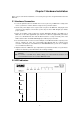
Chapter 3 Configure through Web Browser Web configuration provides a user-friendly graphical user interface (web pages) to manage your WRT-415. 1. Open your web browser. 2. Enter the IP address of your WRT-415 in the address field (default IP address is http://192.168.1.1). 3. A User Name and Password dialog box will appear. Please enter your User Name and Password here. Default User Name and Password are both “admin”. Click “OK”. 4. When the first time you enter WRT-415, Setup Wizard will pop up.
mask, and domain name. LAN and DHCP profiles are listed in the DHCP table at the bottom of the screen. Host Name: Type the host name in the text box. The host name is required by some ISPs. The default host name is "AP-Router." IP Address: This is the IP address of the router. The default IP address is 192.168.1.1. Subnet Mask: Type the subnet mask for the router in the text box. The default subnet mask is 255.255.255.0.
MAC Address: If required by your ISP, type the MAC address for the WRT-415 WAN interface in this field. You can also copy the MAC address of your PC’s network card to the WRT-415 WAN interface by clicking “Clone MAC address”. When using PPPoE, enter the following information in the fields (some information are provided by your ISP): WAN IP: Select whether you want the ISP to provide the IP address automatically, or whether you want to assign a static IP address to the WRT-415 WAN interface.
When using PPTP, enter the following information in the fields (some information are provided by your ISP): Dynamic IP / Static IP: Select the IP assignment method. IP Address: Type the IP address which your ISP provides. Subnet Mask: Type the Subnet Mask which your ISP provides. Gateway: Type the IP address of Gateway which your ISP provides. DNS: Type the IP address of DNS server which your ISP provides. Server IP/Name: Type the IP address or name of server which offers Internet service.
When using L2TP, enter the following information in the fields (some information are provided by your ISP): Dynamic IP / Static IP: Select the IP assignment method. IP Address: Type the IP address which your ISP provides. Subnet Mask: Type the Subnet Mask which your ISP provides. Gateway: Type the IP address of Gateway which your ISP provides. DNS: Type the IP address of DNS server which your ISP provides. Server IP/Name: Type the IP address or name of server which offers Internet service.
Administrator: Type the password the Administrator will use to login to the system. The password must be typed again for confirmation. User: Users can type a password to be used for logging in to the system. The password must be typed again for confirmation. 3.1.4 Time This screen enables you to set the time and date for the router's real time clock, select your time zone, specify an NTP server, and enable or disable daylight saving. Local Time: Displays the local time and date.
Set the Time: Select the date and time from the pull-down lists, and click “Set Time” to set the WRT-415's internal clock to the correct date and time. Daylight Saving: Enables you to enable or disable daylight saving time. When enabled, select the start and end date for daylight saving time. 3.1.5 Dynamic DNS You can configure WRT-415 to use DDNS service if you already have a registered DDNS account. DDNS: You can enable or disable DDNS function here.
Wireless Radio: Enable or disable wireless LAN via the WRT-415. SSID: Type an SSID in the field. The SSID of any wireless device must match the SSID typed here in order for the wireless device to access the LAN and WAN via the WRT-415. Channel: Select a work channel for wireless communications. The channel of any wireless device must match the channel selected here in order for the wireless device to access the LAN and WAN via the WRT-415. 3.2.
WEP Key: Select the level of encryption you want from the drop-down list. WRT-415 supports 64, and 128-bit encryption. Key 1 ~ Key 4: There are 4 keys available, please ensure you have enter correct number for the key values with different Key Length and coding (Hex or ASCII) as 64bit (10 Hex digit / 5 ASCII), 128bit (26 Hex digit / 13 ASCII) or 256bit (58 Hex digit / 29 ASCII), please select one of them and enter the key you want to use. Click “Clear” to erase key values.
3.2.3 Advanced This screen enables you to configure advanced wireless functions. Beacon Interval: Type the beacon interval in the field. You can specify a value from 1 to 1000. The default beacon interval is 100. RTS Threshold: Type the RTS (Request-To-Send) threshold in the field. This value stabilizes data flow. If data flow is irregular, choose values between 256 and 2432 until data flow is normalized. Fragmentation Threshold: Type the fragmentation threshold in the field.
SSID Broadcast: If disabled, no SSID is broadcast. If enabled, the SSID of WRT-415 will then be broadcast to all wireless stations. Stations which have no SSID (or a "null" value) can then adopt the correct SSID for connections to this router. 3.3 Status 3.3.1 Device Information This screen enables you to view the router LAN, wireless LAN, and WAN configuration. Firmware Version: Displays the latest build of the WRT-415 firmware.
3.3.2 Log This screen will show you a running log of system statistics, events and activities. The log displays up to 200 entries. Older entries are overwritten by new entries. You can save logs via the Log Settings option -> “Send to”. The Log screen commands and information meaning are as follows First Page: View the first page of the log message list. Last Page: View the last page of the log message list. Previous Page: View the page just before the current page.
SMTP Server: Type the SMTP server address for the email that the log will be sent to in the next field. Send to: Type an email address for the log to be sent to. Click “Email Log Now” to send the current log immediately. Syslog Server: Type the IP address of the Syslog Server if you want the WRT-415 to listen and receive incoming SysLog messages. Log Type: Select what items will be included in the log: System Activity: Displays information related to WRT-415 operation.
3.3.5 Wireless This screen will show you which wireless devices that are connected to this WRT-415 via wireless interface. Connected Time: Displays how long the wireless device has been connected to the LAN via the WRT-415. MAC Address: Displays the devices wireless LAN interface MAC address. 3.4 Routing 3.4.1 Static You can set parameters by which the WRT-415 forwards data to its destination if your network has a static IP address.
Network Mask: Type the network (subnet) mask for your network. If you do not type a value here, the network mask defaults to 255.255.255.255. Your ISP or network administrator provides you with this information. Gateway Address: Type the gateway address of your network. Your ISP or network administrator provides you with this information. Interface: Select the interface WAN or LAN that you will use to connect to the Internet. Metric: Select which metric you want to apply to this configuration.
Network Address: Displays the network IP address of the connected node. Network Mask: Displays the network (subnet) mask of the connected node. Gateway Address: Displays the gateway address of the connected node. Interface: Displays whether the node is connected via a WAN or LAN. Metric: Displays the metric of the connected node. Type: Displays whether the node has a static or dynamic IP address. 3.5 Access 3.5.
Only allow computers … : All users are denied Internet access except those users listed in MAC table. Only deny computers … : All users are allowed Internet access except those users listed in MAC table. MAC Table: Use this field to create a table to which Internet access is denied or allowed. The user profiles are listed in the table below. Note: When selecting items in the table at the bottom, click anywhere in the item.
Edit Protocol Filter in List: Use this section to create a profile for the protocol you want to deny Internet access to. Enable: Click to enable or disable the protocol filter. Name: Type a descriptive name for the protocol filter. Protocol: Select the protocol (TCP, UDP or ICMP) you want to deny Internet access to from the pull-down list. Port Range: If you are creating a profile for ICMP, type a minimum and maximum port range in the two fields.
3.5.4 Virtual Server This screen enables you to create a virtual server via the WRT-415. If the WRT-415 is set as a virtual server, remote users requesting Web or FTP services through the WAN are directed to local servers in the LAN. The WRT-415 redirects the request via the protocol and port numbers to the correct LAN server. The Virtual Sever profiles are listed in the table at the bottom of the page. Enable: Click to enable or disable the virtual server.
Enable: Click to enable or disable the application profile. When enabled, users will be able to connect to the application via the WRT-415 WAN connection. Click Disabled on a profile to prevent users from accessing the application on the WAN. Name: Type a descriptive name for the application. Trigger: Defines the outgoing communication that determines whether the user has legitimate access to the application. Protocol: Select the protocol (TCP, UDP or ICMP) that can be used to access the application.
Enable: Click to enable or disable the DMZ. DMZ Host IP: Type a host IP address for the DMZ. The computer with this IP address acts as a DMZ host with unlimited Internet access. Apply: Click to save the settings. Note: Any clients added to the DMZ exposes the clients to security risks such as viruses and unauthorized access. 3.5.7 Firewall Rule This screen enables you to set up the firewall.
Enable: Click to enable or disable the firewall rule profile. Name: Type a descriptive name for the firewall rule profile. Action: Select whether to allow or deny packets that conform to the rule. Inactive Timeout: Type the timeout period in seconds in this field. If the network is inactive for the specified duration, the router refuses the incoming packet. Source: Defines the source of the incoming packet that the rule is applied to. Interface: Select which interface (WAN or LAN) the rule is applied to.
3.6 Management 3.6.1 Remote Management This screen enables you to set up remote management. Using remote management, the WRT-415 can be configured through the WAN via a Web browser. A user name and password are required to perform remote management. HTTP: Enables you to set up HTTP access for remote management. Enable: Click to enable or disable HTTP access for remote management. Remote IP Range: Type the range of IP addresses that can be used for remote access.
3.7.2 Settings This screen allows you to save settings as a profile and load profiles for different circumstances. You can also load the factory default settings, and run a setup wizard to configure the WRT-415 and WRT-415 interface. VPN Pass-Through: The WRT-415 supports VPN pass-through for both PPTP and IPSec. Once the VPN pass-through is enabled, there is no need to configure virtual server settings. Multiple VPN connections can be made through the router.
Load Settings: Click “Browse” and go to the location of a stored profile. Click Load to load the profile's settings. Restore Factory Default Settings: Click to restore the default settings. All configuration changes you have made will be lost. 3.7.3 Firmware You can upgrade your WRT-415 with new firmware in this screen. Please follow these instructions: 1. Download the latest firmware from PLANET's website, and save it to your disk. 2. Click “Browse” and find out the location of the downloaded file. 3.
3.8 Wizard The setup wizard enables you to configure the WRT-415 quickly and conveniently. Click “Wizard” button, the window below will appear. Please click “Next>” and follow the steps to configure WRT-415. You are prompted to select a password. Type a password in the text box, and then type it again for verification. Click Next. Select your time zone from the drop-down list. Click Next. Type the LAN IP address in the text box. The default IP address is 192.168.1.1. Type the subnet mask in the text box.
Appendix A TCP/IP Settings for PC The network TCP/IP settings differ based on the computer’s operating system (Win95/98/ME/NT/2000/XP) and are as follows. Windows 95/98/ME 1. Click on the “Network neighborhood” icon found on the desktop. 2. Click the right mouse button and a context menu will be show. 3. Select “Properties” to enter the TCP/IP setting screen. 4. Select “Obtain an IP address automatically” on the “IP address” field. 5. Select “Disable DNS” in the “DNS” field.
6. Select “None” for the “Gateway address” field. Windows 2000 Double click on the “My computer” icon on the desktop. When “My computer” window opens, open the “Control panel” and then open the “Network dialup connection” applet. Double click on the “Local area network connection” icon. Select “Properties” to enter the TCP/IP setting window. 1. In the “Local area network status” window, click on “Properties.” 2.
Windows XP Point the cursor and click the right button on the “My Network Place” icon. Select “properties” to enter the TCP/IP setting window. 1. Set “IP address” to “Obtain an IP address automatically.” 2. Set “DNS” to “Obtain DNS server address automatically.