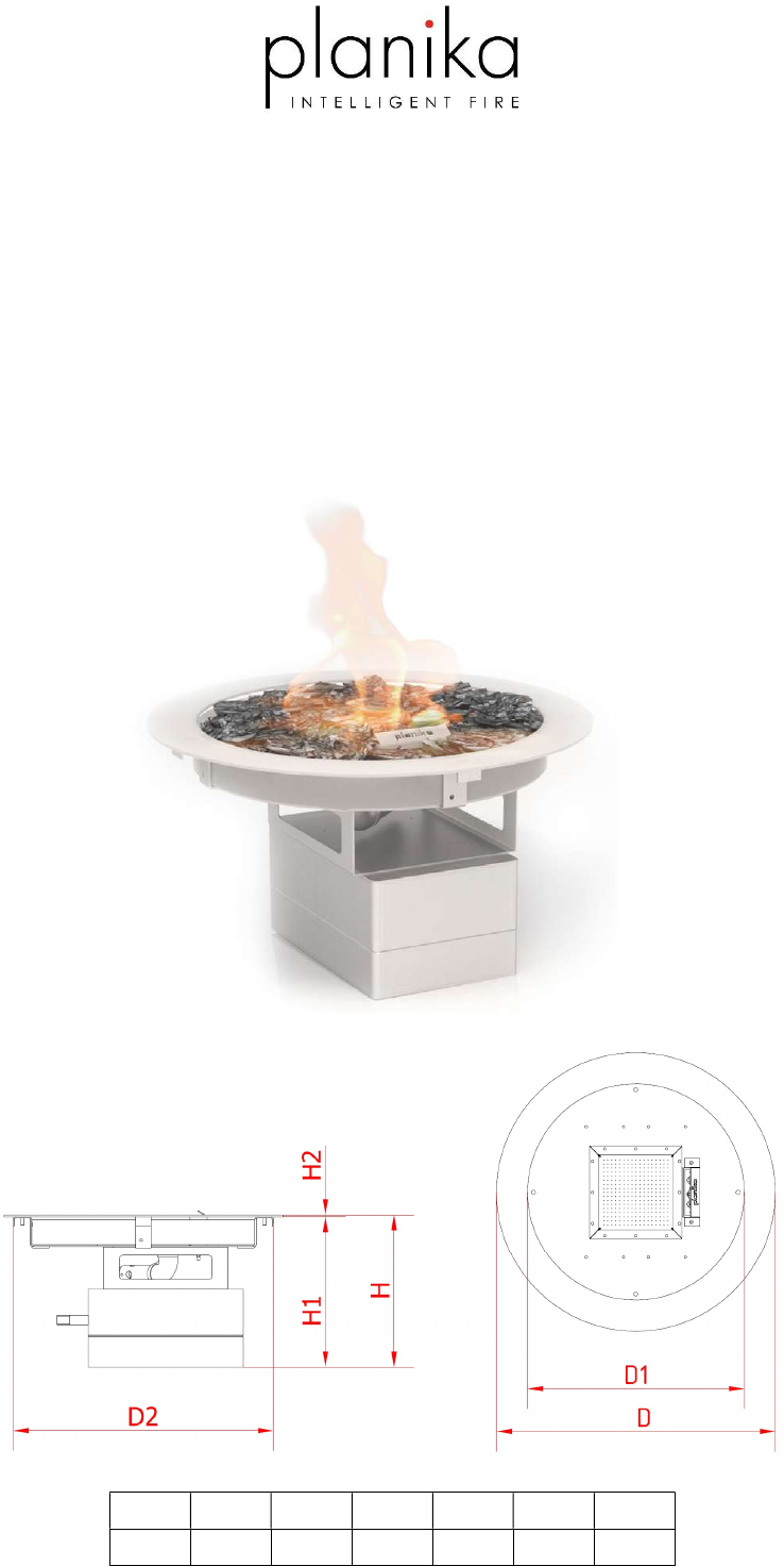
USER’S and INSTALLATION MANUAL GaLiO Fire Pit Insert Natural Gas/Propane-Butane/Propane [mm] Copyright Planika Sp. z o.o. H 250 H1 247 www.planikafires.com H2 3 D 450 IG0031#05 D1 350 D2 420 10.10.
IT IS OBLIGATORY TO READ AND KEEP THIS INSTRUCTION MANUAL. TABLE OF CONTENTS 1. INTRODUCTION ......................................................................................................................................................... 4 2. SAFETY INSTRUCTION ............................................................................................................................................... 6 2.1 3. 4. INSTALLATION ..................................................................
9. PRESSURE ADJUSTMENT ......................................................................................................................................... 37 10. ELECTRICAL DIAGRAMS ....................................................................................................................................... 40 11. TECHNICAL SPECIFICATION ................................................................................................................................. 41 12.
1. INTRODUCTION The GaLiO Fire Pit Insert fireplace is a decorative fuel-effect gas appliances intended only for outdoor use. It is obligatory to acquaint oneself with the below installation manual and user’s manual before committing to the installation and use of the GaLiO Fire Pit Insert fireplace. This manual is to be kept safe for the lifetime of the device. The Planika company designs and manufactures gas devices that meet the highest standards of quality, and safety.
INSTALLATION NOTICE The installation of this appliance is only to be carried out by an authorized person in accordance with the Manufacturers Instructions, local gas fitting regulations, AS/NZS5601.1-2013 installation code for gas burning appliances and any other relevant statutory regulations. In all cases the installation of this appliance shall meet the requirements as set out in AS/NZS5601.1-2013 IMPORTANT SAFETY NOTICES DO NOT PLACE ARTICLES ON OR AGAINST THIS APPLIANCE.
2. SAFETY INSTRUCTION Read the instructions before use. Keep the instructions for future reference. For use outdoors only. The use of this appliance in enclosed areas is DANGEROUS and is PROHIBITED The GaLiO Fire Pit Insert is not a free-standing device and is destined to be housed. The montage of the device must take into account its trouble-free removal in case of service. Do not start up the device before it’s placed safely into the prepared housing.
2.1 Safety instruction regarding the use of the gas cylinder Use only the type of gas and pressure specified by the manufacturer. The gas cylinders should always be placed in a vertical position – during use and transport. Always store the gas cylinder in an easily accessible place to allow its immediate turn-off. Change the gas cylinder in a amply ventilated area, away from any ignition source (candle, cigarettes, other flame producing appliances).
3. INSTALLATION 3.1. Box contents 1x complete gas fireplace 1x Wall Switch 1x Remote control (if delivered) 4x AA Batteries 2x AAA Batteries (if remote delivered) 4x bag of decorative stones 1x 4 metre rubber gas linkage – installed (only LPG version) 1x pressure regulator– installed (only LPG version) 1x installation and user’s manual 3.2. Unboxing and installation The contents of the boxes need to be carefully unwrapped from the foam foil.
4. MONTAGE WARNING!!! All elements above the fireplace need to be made of non-flammable materials. Select a location where the outdoor fire can be supervised during operation. The outdoor fire is suitable for outdoor use only and must not be used indoors. An isolation switch must be fitted at the appliance or on an adjacent wall to allow for emergency shutdown and maintenance. Installation must meet Australian gas codes AS/NZS5601.1-2013.
In accordance with fire safety measures there should be no flammable objects in direct Non-flammable materials contact with the device nor within a 1 metre radius from the fire. Additionally, Planika doesn’t recommend placing heat-sensitive objects above the fireplace as it may shorten their lifetime. Planika will not be responsible for any damage caused by high temperature affecting objects installed above the fire. Ventilation grate or slot with ventilation area of minimum 150cm2 Copyright Planika Sp.
Nonflammable materials The dimensions of the housing are to be chosen according to the technical drawings and a ventilation grid or slot – with ventilation area min 150cm2 – needs to be placed near the base of the unit, minimally 110 mm below the burner surface. If a hood is placed above the burner it needs to be made of non-flammable materials and a minimum distance of 60 cm from the surface of the burner needs to be observed.
4.3 Directions of how to design a housing for the fireplace Enclosure must be stable and be constructed of non-combustible materials. Enclosure and fire must be installed above ground level and have adequate drainage. The enclosure must have a ventilation slot with open area of minimum 150cm2. Ventilation allows for residual heat and unburnt gases to escape the enclosure. Gas fire pits must be assessed and certified to AS 5263.0 Gas appliances and the below additional requirements.
Ventilation grate or slot with ventilation area of minimum 150cm2 Make the cavity for the insert according to the below outline. When preparing the cavity make sure the surface on which the insert is placed is well-levelled as there is no option of levelling out the insert. WARNING! The level difference between the edges of the fireplace cannot exceed 2 mm. Incorrect levelling may cause incorrect operation of the device and in a worst case scenario, a fire.
The level difference between the edges of the fireplace cannot exceed 2 mm. Incorrect levelling may cause incorrect operation of the device and in a worst case scenario, a fire. Level the plane of the cavity. The level deviation must not exceed 2 mm 4.3.1 Glass cylinder installation Protective glass cylinder shall be installed on the top of the burner. Place glass cylinder on the 4 mounting bracket at secure it gently with the 4 screws Copyright Planika Sp. z o.o. www.planikafires.
Copyright Planika Sp. z o.o. www.planikafires.com IG0031#05 10.10.
4.4 Gas cylinder montage WARNING! In case of LPG version it is crucial to manufacture a slot in the side of the housing where the insert is placed for the gas linkage and the pressure regulator. The gas linkage attached to the device allows to place the gas cylinder maximally 3 metres away from the connected control panel, however it cannot be placed nearer to the device than 1,5 metres. Copyright Planika Sp. z o.o. www.planikafires.com IG0031#05 10.10.
The optional housing for the gas cylinder cannot be airtight and has to be correctly ventilated. The housing needs to have an upper ventilation slot above the top of the bottle (of an area min 1/100 of the area of the base of the housing, not less than 10,000mm2 ) and a lower ventilation slot (of an area min 1/50 of the area of the base of the housing, not less than 6,000mm2).
WARNING!!! • After making sure that the device has been correctly installed acquaint yourself with the attached User’s Manual. • Only after acquainting yourself with the User’s Manual and correctly attaching the gas linkage may you start the device. • If in future a need arises of having to take the insert out of the housing it may only be done when the device is turned off and cooled down and the valve on the gas cylinder is closed. • Keep this instruction manual for the lifetime of the device. 4.
The GaLiO Fire Pit Insert fireplace can use metal or steel bottles or composite bottles filled with propane-butane gas or propane gas. WARNING!!! NEVER use an unstable gas connection or a regulator for other gas pressure. Gas cylinders have two types of connectors: Twist-on connection: The most important thing is the black seal. Always check if the seal is present and that it hasn't been damaged during the gas cylinder replacement.
5. When the gas flow is required turn the valve of 4. To let the gas flow in turn the switch into the ON the bottle counter-clockwise. position (or into the flame image). Place the gas cylinder in a correct distance from the fireplace (min 1,5 metres away). WARNING!!! Check the gas connection for leakage. If anything suggests a leak is present (for instance a characteristic gas smell) close the gas cylinder valve and under no circumstances turn the device on before removing the leak.
5. REPLACE the linkage closer or cap on the empty or partially full bottle if it’s not being used. 4. REPLACE the tightening cap on an empty or partially full bottle if it’s not being used. 4.5.3 Pressure regulator replacement (LPG version) 1. You always need to use a pressure regulator between the gas cylinder and the device. Replace the pressure regulator every 5 years. Allowed pressures: 30 mbar, 37 mbar (recommended), 50 mbar. Use only the redactors that comply with the EN16129 European Norm. 2.
6. Take off the linkage from the stub of regulator. 7. Attach a new linkage on the stub of regulator. 8. Move the clamp into the stub again and tighten it. WARNING! In the event of visible damage on the clamp, replace it for a new one. Copyright Planika Sp. z o.o. www.planikafires.com IG0031#05 10.10.
5. OPERATING INSTRUCTIONS The GaLiO Fire Pit Insert fireplace has a remotely control valve with a built-in ignition for the pilot flame. The flame height of the main burner may be appropriately regulated by Wall Switch (Touch Panel) or remote control (if delivered). Hand-held transmitter and Wall Switch 5.1 Setting up signal code WARNING! You only need to set up the signal code once. It is not necessary when changing the batteries of the handheld transmitter or receiver.
5.2 Installing the control unit (Wall Switch) The control unit has standard a cable with a length of 8 m (connection for battery supply and for the controlling). NOTE: The cables may not be extended. Longer cables can pick up environmental signals that can switch the appliance uncontrolled On or Off. Determine the location for the control unit (Wall Switch). Pull the cables through the opening of 5 x 8 cm on the surface on which Wall Switch will be mounted.
5.3 Replacing the batteries If the batteries are inserted incorrectly, the electronics or drive may be irreparably damaged. Only replace the batteries when the appliance has been completely switched off. NOTE: If the appliance is equipped with a 230 VAC connection, no batteries are present in the receiver or in battery box. The battery are placed in battery holder which is integrated into the control unit (Wall Switch). Unscrew the Wall Switch plate. Remove the battery holder.
Replace 4 pieces of AA/LR6 Alkaline long live batteries. Replace the battery holder and mount the Wall Switch plate. Screw the Wall Switch plate. 5.4 Remote control (if delivered) GaLiO Fire Pit Insert can be operated by radio remote control. This comprises a hand-held transmitter and a receiver. The receiver is part of the gas control block assembly. Electrical connections and batteries: o Hand-held transmitter: 2x 1.5V AAA battery o Receiver: 4x1.
5.4.1 Switch the Fire ON and OFF Before operating make sure MANUAL knob on the GV60 valve is in the ON, full counter clockwise position. WARNING! When the pilot light is ignited, the motor turns automatically to maximum flame height. If the pilot flame goes out for any reason, wait for 5 minutes before attempting to re-light it. If the pilot does not stay lit after several tries, turn the main valve knob to OFF. 1. Open the valve of the gas cylinder (or gas supply valve in the gas pipe). 2.
WARNING!!! Under conditions of increased humidity (rain, breeze, fog, dew, etc.), there may be some temporary problems with switching on the fireplace. This is a normal phenomenon associated with the dampening of the ignition element. Before switching on the fireplace, wait until the ignition element has dried completely. You can speed up this process by blowing the pilot flame with compressed air to remove the accumulated moisture. The properly fired pilot flame consist of 3 smaller parts. 5.4.
5.4.3 Flame height adjustment After ignition, the burner automatically sets the flames to the maximum height. To decrease flame high, or to set appliance to pilot flame, press high press and hold „-“ button. To increase flame and hold „+“ button. 5.4.4 Flame height directly to minimum position Pressing the „-“ button twice automatically decreases the flames to the LOW position NOTE: Flame goes to high fire first before going to low fire.
5.4.5 Flame height directly to maximum position Pressing the „+“ button twice automatically decreases the flames to the HIGH position Press and hold „+“ button to increase the flame level and to turn on the burner from the stand-by position. NOTE: If you turn on the burner by pressing the button, it must ignite within 10 seconds. If this does not happen, immediately close the gas tap and warn the fitter. 5.4.
5.4.7 Automatic Shut Off Countdown Timer At end of countdown time period, the fire shuts off. The Countdown Timer only works in Manual, Thermostatic, and Eco Modes. Maximum countdown time is 9 hours and 50 minutes. Low Battery Receiver With low battery power in the receiver the system shuts off the fire completely. This will not happen if the power supply is interrupted. On-Demand Pilot This green feature eliminates gas energy consumption during extended appliance inactivity.
5.5 Wall Switch Depending on customers preferences GaLiO Fire Pit Insert may be additionally operated either by Wall Switch (included) or Touch panel. Both can be placed maximum 8 meters away from the Insert. Additionally behind Wall Switch the battery box can be placed. Wall Switch and Touch Panel To Turn ON Appliance Press ON-OFF button until two short beeps confirm the start sequence has begun; release button. Once pilot ignition is confirmed, there is main gas flow.
6. TESTING WARNING!!! NEVER TURN ON THE DEVICE IF THE CHARACTERISTIC SMELL OF GAS IS PERCEPTIBLE. If you smell gas during the operation of the fireplace turn off the device immediately and cut off the gas supply from the gas cylinder by shutting its valve. 6.1 Checking for gas leaks Check if all connections are airtight. To do that apply all connections with soapy water (or water with another foamy substance) or with a professional spray for leak detection.
7. MAINTENANCE AND UPKEEP We recommend cleaning the pilot flame and the main burner unit before the device is started again after its been removed from storage during the winter period. 7.1 Testing and cleaning Please check and clean if necessary: The main burner - if necessary, remove broken parts of stones and the existing dust. Pilot burner and thermo-couple (if necessary, remove the existing sediment). In the event of visible damage contact your dealer.
8. TROUBLESHOOTING Warning! Montage, upkeep and service need to be conducted by a qualified professional with appropriate qualification, an appropriate company or the gas supplier. PROBLEM SMELL OF GAS Leak detected at cylinder, regulator or other connection. Burner does not ignite POSSIBLE CAUSE CORRECTIVE ACTION CLOSE THE VALVE ON THE GAS CYLINDER IMMEDIATELY. DO NOT USE THE DEVICE UNTIL LEAKS HAVE BEEN REMOVED. 1. A loose regulator linkage. 1. Tighten and test it. 2. Leak in the gas linkage, in the 2.
There are many factors that may affect the malfunction of the gas insert. To exclude a possible fault in the unit or the automatic gas control system, make sure that the fireplace is connected according to these instructions. Below table summarizes possible failures that may occur, possible causes and ways to solve them. Copyright Planika Sp. z o.o. www.planikafires.com IG0031#05 10.10.
9. PRESSURE ADJUSTMENT Do not attempt to remove screws from the top of gas valve. Do not change any adjustments marked with tamper indicating paint. Motor knob is not to be removed. Pilot Flame Adjustment The pilot flow adjustment is preset to maximum at the factory. The pilot flame should envelope ⅜ to ½ of the thermocouple o The adjustment screw can be reached through a hole in the MANUAL knob (see figure 21). o Turn the MANUAL knob to the ON position.
Outlet Pressure Adjustment (High Fire) o Connect a pressure manometer to the valve outlet pressure tap. Pressure tap is opened by turning the screw counterclockwise. Pressure regulator or throttle are located under the cover and can be reached by removing the plug (see figures 21 and 23). o Turn MANUAL knob and main valve knob to the ON position. o Turn pressure regulator adjustment screw to set required burner pressure (high fire).
Minimum rate Adjustment o Connect a pressure manometer to the valve outlet pressure tap. Pressure tap is opened by turning the screw counterclockwise. Minimum rate adjustment screw is located on the top of the metal valve body. o Turn minimum rate adjustment screw to set required burner pressure (minimum fire).
10.ELECTRICAL DIAGRAMS Copyright Planika Sp. z o.o. www.planikafires.com IG0031#05 10.10.
11.TECHNICAL SPECIFICATION Copyright Planika Sp. z o.o. www.planikafires.com IG0031#05 10.10.
12.MANUFACTURER’S CONTACT DETAILS Company Name: Address: Telephone: Fax: Copyright Planika Sp. z o.o. Planika Sp. z o.o. Bydgoska 38 86-061 Brzoza Poland + 48 52 364 11 60 + 48 52 364 11 70 www.planikafires.com IG0031#05 10.10.