
Use and Care Manual

061119-1
Plastic Development Group, LLC, Southfield, MI 48075 • www.plasticdevelopmentgroup.com Made in China
Step 8:
Attach the
Gas Shocks to
the two round
nubs on the
Bracket/Hinges
by pushing bothby pushing both
ends until you
hear a “snap”.
UP
Top
End
Gas
Shock
Bottom
End
Gas
Shock
Step 7:
Attach the
Gas Shock
Bracket/Hinge
to the inside
of the Lid with
4 Sel4 Self-Tapping
Screws (A)
each.
A
A
A
A
R
L
Side Panel
Lid Panel
Gas Shocks
Bracket/Hinges
Step 6:
Position a Bracket/
Hinge into grooves
at the top inside
corner of the Back
Panel. (Fig 1)
Secure in place withSecure in place with
3 Machine Screws.
Use 2 Machine Screws
(B) to attach the Bracket
to the Side Panel (Fig 2).
Use 1 Machine Screw (B)
to attach the Bracket to
the Back the Back Panel (Fig 3).
Repeat for the other
Bracket/Hinge.
B
Fig 3
B
B
Fig 2
Fig 1
Step 5:
Hold the Lid Panel
horizontally and line
up the Lid Tabs with
Back Panel Hinge
Pins. Push Lid Panel
horizontally intohorizontally into
Back Hinge Pins
and rotate the Lid
closed to lock into
place.
Hinge Pins
Lid Panel
Lid Tabs
Step 4:
Slide Front Panel into
position using the slots
at the front of the Side
Panels. Press the Lock-
Tabs into the slots in
the Bottom the Bottom Panel to
lock in place.
Lock-Tab Slots
Side Panel
Front Panel
Step 3:
Slide Back Panel into
position using the slots
at the rear of the Side
Panels. Press the Lock-
Tabs into the slots in the
Bottom Bottom Panel to lock in
place.
Lock-Tab Slots
Side Panel
Back Panel
Step 2:
Slide a Side Panel onto
the Bottom Panel then
repeat with the other.
Bottom Panel
Side Panel
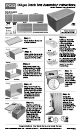
Step 1:
Place Bottom Panel on
a level surface.
Bottom Panel
Lid Support (pre-assembled on panel)
Gas Shocks
RL
Gas Shock
Bracket/
Hinges
x 6
Machine Screws
x 8
Self-Tapping
Screws
Bottom PanelLid Panel
Back PanelFront PanelSide Panels (2 pcs)
Parts Included:
Patent
Pending
Tools Needed:
Philips Head Screwdriver
Item Nos.: DB1305WLJ-GS & DB130WLG-GS
130
gal
Deck Box Assembly Instructions