
Operation Manual


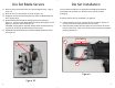

6) RaiseBladeovertheguidepostsperFigure13anddisengageBlade
Tabs(a)fromBladeReturnSprings.
7) RemoveandreplaceBladeSpacerandBladeReturnSpringsasre‐
quired.LubricateBladeSpacerandNewBladewithlightmachine
oil.
8) ReassemblediewithnewBladeinreverseorderof“BladeService”
steps4‐7.Note:ToeaseBladeTabinsertionintoBladeReturn
Springs,positionspringsontheBladeGuidePostsasshownin
Figure14(a).EnsureBladerestsflatagainstBladeSpacerpriorto
slidingBladeGuideBlockontotheassembly.
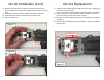
9) TightenBladeRetentionNutsuntilsafetywireholesarevisibleinthe
BladeGuidePostsperFigure15(a).Insertapproximately3”of
SafetyWirethrougheachholeandsnuglytwistwiretogether3‐5
times.
10)ClipexcessSafetyWirefromeachpostperFigure10(a)andbend
twistedportionaroundthepostperFigure1topreventsnagging
duringuse.
11)Re‐installdieintoolframeper“DieSetInstallation”steps1‐6.
DieSetBladeService(cont)
10
Figure13
a
a
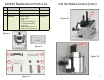
Operation
The100544EZ‐VIKINGCrimpToolismanufacturedtoprovideanexcep‐
tionallypreciseandrepeatablecrimptolerancewhichwillmaximizenet‐
workperformanceaftertermination.Propermaintenanceandcareas
detailedinthismanualwillensurealongservicelife.
ThistooliscompatiblewithallEZ‐RJ45
®
Cat5e,Cat6,Cat6Internaland
ExternalGroundconnectors.
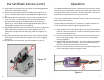
Preparecablepermanufacturer’sinstructions.Prepareandwirecon‐
nectorasdefinedbynetworkengineeringspecifications.
1) TwistconductorsintoabundleperFigure4toensureeasyinsertion
intotool.Twisttheconductorsatthefarendkeepingthemtension
freeattheconnectorface(a).
2) Inserttwistedconductorsandconnectorintotooldieuntilthecon‐
nectorlockingtabengages.Note:Asmall“click”willbeaudible
duringengagement.
3) Whileholdingtwistedconductorsinonehand,squeezetoolhandles
togetheruntiltheratchetreleases.Thetoolsimultaneouslytrims
theexcessconductorsandcrimpstheconnector.
4) Removecrimpedconnectorfromthetooldiebydepressingthecon‐
nectorlockingtabandgentlypullingthecable.
Figure4
a
3