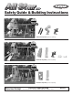
Safety Guide & Building Instructions PS 8860 PS 7956 PS 8820 Featured Components (purchase separately): PS 8850 PS 8813 PS 7956 PS 7668 PS 7690 Featured Components (purchase separately): PS 8870 PS 8813 Featured Components (purchase separately): We’re Here To Help! Call Toll Free 1-888-752-9782 Customer Service: Monday - Friday, 8:00 A.M. to 5:00 P. M. C.S.T.
SAFETY • Follow the instructions provided, do not alter its design in any way. • This product is intended for single-family residential use only, by children ages two to ten and a maximum weight of 105 pounds. Any recommendation over 10 years of age or 105 pounds exceeds the upper limits specified in the American Society for Testing and Materials (ASTM) Home Playground Safety Standard. In order for PlayStar to comply with the ASTM Standard, we cannot recommend anyone above these limits.
SAFETY INSTALLATION: 1. Follow the instructions provided, do not alter its design in any way. 2. Place the playset on level ground, not less than 6' (1.8m) from any structure or obstruction such as a fence, garage, house, overhanging branches, laundry lines or electrical wires. If the area where you will be installing your playset is not level, you must make it level. 3. Playsets must be anchored to the ground. Follow the anchoring instructions provided with your building kit.
INDEX COMPONENTS INCLUDED Instructions for all three design options are included in this plan All Star XP Contents: NOTE: If you are adding the Optional Adventure Tunnel Kit or Climbing Bar Kit, you will want to familiarize yourself with all instructions as some steps may be repeated. 1 1 pr 2 pr 1 4 2 3 1 4 4 5 1 • • Drill Template Instructions . . . . . . . . . . . 6 Gold Cutting Guide . . . . . . . . . . . . . . . 8 Roof Assembly . . . . . . . . . . . . . . . . . . . 10 Tower Assembly . . . . . . .
MINIMUM USE ZONE All Star XP “Gold” Dimensions and Area Requirements. Lumber and Screw Requirements (4) (3) (3) (5) (1) 4" 4" 2" 2" 2" x x x x x 4" 4" 6" 6" 4" x x x x x 10' 8' 10' 8' 10' (11) (4) (6) (449) 2" x 4" x 8' 5/4" x 6" x 10' 5/4" x 6" x 8' #8 x 2¹ ₂" Deck Screws GOLD CUTTING GUIDE AND BUILDING INSTRUCTIONS BEGIN ON PAGE 8 MINIMUM USE ZONE All Star XP “Silver” Dimensions and Area Requirements.
How To Use Your Marking Template for Drill Holes: Warning: Do not drill holes through the template as you may damage the template. Use an ¹ ₈" drill bit for all holes unless noted (see patterns G & J) Note: When the PlayStar logo is showing, the three tabs on the bottom will position the template square with any two edges. When the arrow is showing, the two tabs on the bottom will position the template square with one edge only, which will allow you to slide the template anywhere along the board.
PLEASE NOTE (Letters represent pattern not position) E Pattern H I and J can be created anywhere along the board by turning the template over (arrow side up) and sliding it to the desired position. Use the shaded holes for that pattern.
CUTTING GUIDE - GOLD Before starting to build your Playset, make sure all boards are cut and identified by size. Stack identical size boards in neat piles. (If you do not want to mark on lumber, use masking tape or chalk.) This will improve your building time greatly because you will already know the size of each board as the instructions call for them.
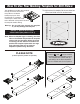
2" x 4" x 10' – one (1) board required (1) board 28¹ ₂" 38" 26¹ ₂" 26¹ ₂" 2" x 4" x 8' – eleven (11) boards required 48" (3) boards 60¹ ₂" (2) boards (2) boards (1) board (1) board 35" 38¹ ₂" 24¹ ₄" 28¹ ₂" 24¹ ₄" 28¹ ₂" 21¹ ₄" 48" (1) board (1) board 48" 11" 38¹ ₂" 21¹ ₄" 11" 11" (Tube Slide Base) 11" 38¹ ₂" 38" 38" 5/4" x 6" x 10' – four (4) boards required (3) boards (1) board 28¹ ₂" 28¹ ₂" 28¹ ₂" 24" 28¹ ₂" 21¹ ₂" 28¹ ₂" 21¹ ₂" 21¹ ₂" 5/4" x 6" x 8' – six (6) b
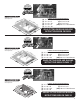
38¹|₂" 38¹|₂" ROOF ASSEMBLY - GOLD Items for STEP 1: (2) (2) (2) (12) 2" x 4" x 38¹⁄₂" boards 2" x 4" x 35" boards Roof Caps #14 x 1¹⁄₄" pan head screws 38¹|₂" On a flat surface position boards together as shown. Position roof cap flush with outside edges. Use roof cap as a drill guide and drill ¹⁄₈" holes 1" deep. Keep boards square while attaching roof cap to boards with #14 x 1¹⁄₄" pan head screws. x 2" x 4" 2" x " 35 90˚ 38¹|₂" 4" x 38 ¹₂ " Repeat for second assembly.
TOWER ASSEMBLY - GOLD Items for STEP 1: (2) (1) (1) (1) (3) (4) (4) (48) On a flat surface position boards at dimensions shown. Keep assembly square while securing with #8 x 2¹⁄₂" deck screws. 4" x 4" x 108" boards 2" x 6" x 82¹⁄₄" board 2" x 6" x 66¹⁄₂" board 2" x 6" x 48" board 2" x 4" x 48" boards ³ ₈" x 3" lag screws ³ ₈" washers #8 x 2¹⁄₂" deck screws Install ³ ₈" x 3" lag screws with ³ ₈" washers at G and J .
Items for STEP 3: (2) (5) (4) (4) (56) 2" x 4" x 28¹⁄₂" (5) 2" x 6" x 60" boards 2" x 4" x 28¹⁄₂" boards ³ ₈" x 3" lag screws ³ ₈" washers #8 x 2¹⁄₂" deck screws B 92¹|₂" Position boards between assemblies as shown. Keep square while securing with #8 x 2¹⁄₂" deck screws. 53¹|₂" J Note: If you are using 2" x 6" lumber for your deck boards in place of 5/4" x 6" lumber, this dimension must be 58¹ ₂". The reason is 2" x 6" lumber is ¹ ₄" thicker than the 5/4" x 6" lumber called for in this plan.
Items for STEP 5: (1) (4) (2) (2) (2) Step 4 Assembly #8 x 1¹⁄₄" deck screws ³ ₈" x 2" hex bolts ³ ₈" washers ³ ₈" lock nuts Position assembly so that the top and front are flush with the existing boards as shown. Use bracket as a drill guide and drill ¹⁄₈" holes 1" deep into the board. Attach with #8 x 1¹⁄₄" deck screws. Again use the bracket as a drill guide and drill ³⁄₈" holes completely through the board and secure with ³⁄₈" x 2" hex bolt and ³⁄₈" washer and ³⁄₈" lock nut.
Items for STEP 7: Shown without top of tower for easier viewing. (3) 2" x 4" x 38" boards (12) #8 x 2¹⁄₂" deck screws 2" x 4" x 28¹⁄₂" C 12" Position boards flush with the top of the 2" x 4" x 28¹⁄₂" boards. 2" C Secure the two outside boards with four #8 x 2¹⁄₂" deck screws evenly spaced. "x x4 " 38 12" Secure center boards with #8 x 2¹⁄₂" deck screws.
Items for STEP 9: (4) 2" x 4" x 11" boards (32) #8 x 2¹⁄₂" deck screws B Position boards at dimensions shown. Secure with #8 x 2¹⁄₂" deck screws. B 2" x 4" x 11" (4) PATTERN B 92¹⁄₂" 86¹⁄₂" SEE PAGE 6 FOR HOLE PATTERNS Items for STEP 10: (5) 5/4" x 6" x 24" boards (4) 5/4" x 6" x 18" boards (36) #8 x 2¹⁄₂" deck screws Guardrails E Guardrails Position five 5/4" x 6" x 24" boards on the inside of the tower flush with the top and bottom of guardrail boards and equally spaced as shown.
Items for STEP 11: (2) (2) (2) (2) (12) 2" x 4" x 60¹⁄₂" boards 2" x 4" x 26¹⁄₂" boards ³ ₈" x 3" lag screws ³ ₈" flat washers #8 x 2¹⁄₂" deck screws rt po up S ck De 2" x Position two 2 x 4 x 26¹⁄₂" boards (use scrap 2" x 4" board as a temporary spacer for proper alignment) as shown. From inside the tower drill through the 2" x 6" board into the ends of the 2" x 4" x 26¹⁄₂" boards. Secure with #8 x 2¹⁄₂" deck screws. Remove temporary spacers.
CUTTING GUIDE - SILVER Before starting to build your Playset, make sure all boards are cut and identified by size. Stack identical size boards in neat piles. (If you do not want to mark on lumber, use masking tape or chalk.) This will improve your building time greatly because you will already know the size of each board as the instructions call for them.
2" x 4" x 8' – four (4) boards required 48" (2) boards 48" 38¹ ₂" (2) boards 28¹ ₂" 28¹ ₂" 5/4" x 6" x 10' – eight (8) boards required (7) boards (1) board 28¹ ₂" 28¹ ₂" 28¹ ₂" 24" 28¹ ₂" 24" 28¹ ₂" 24" 5/4" x 6" x 8' – one (1) board required (1) board 18 24" 24" 24" 24"
38¹|₂" 38¹|₂" ROOF ASSEMBLY - SILVER Items for STEP 1: (2) (2) (2) (12) 2" x 4" x 38¹⁄₂" boards 2" x 4" x 35" boards Roof Caps #14 x 1¹⁄₄" pan head screws 38¹|₂" x 2" On a flat surface position boards together as shown. Position roof cap flush with outside edges. Use roof cap as a drill guide and drill ¹⁄₈" holes 1" deep. Keep boards square while attaching roof cap to boards with #14 x 1¹⁄₄" pan head screws. x 4" 2" x " 35 90˚ 38¹|₂" 4" x 38 ¹₂ " Repeat for second assembly.
TOWER ASSEMBLY - SILVER Items for STEP 1: (2) (1) (1) (1) (3) (4) (4) (48) On a flat surface position boards at dimensions shown. Keep assembly square while securing with #8 x 2¹⁄₂" deck screws. 4" x 4" x 96" boards 2" x 6" x 82¹⁄₄" board 2" x 6" x 72¹⁄₂" board 2" x 6" x 48" board 2" x 4" x 48" boards ³ ₈" x 3" lag screws ³ ₈" washers #8 x 2¹⁄₂" deck screws Install ³ ₈" x 3" lag screws with ³ ₈" washers at G and J .
Position boards between assemblies as shown. Keep square while securing with #8 x 2¹⁄₂" deck screws. Items for STEP 3: (2) (4) (4) (4) (48) 2" x 6" x 28¹⁄₂" boards 2" x 4" x 28¹⁄₂" boards ³ ₈" x 3" lag screws ³ ₈" washers #8 x 2¹⁄₂" deck screws Install ³ ₈" x 3" lag screws with ³ ₈" washers at G . 2" x 4" x 28¹⁄₂" (4) PATTERN B B 90˚ B 2" x 6" x 28¹⁄₂" (2) PATTERN G 80¹⁄₂" G Note: If you are using 2" x 6" lumber for your deck boards in place of 5/4" x 6" lumber, this dimension must be 46¹ ₂".
Items for STEP 5: Shown without top of tower for easier viewing. (3) 2" x 4" x 38" boards (12) #8 x 2¹⁄₂" deck screws 2" x 4" x 28¹⁄₂" C Position boards flush with the top of the 2" x 4" x 28¹⁄₂" boards. Secure the two outside boards with four #8 x 2¹⁄₂" deck screws evenly spaced. 12" 2" " x4 x3 12" 8" C Secure center boards with #8 x 2¹⁄₂" deck screws.
Items for STEP 7: (4) 2" x 4" x 13¹⁄₄" boards (1) 2" x 4" x 21¹ ₂" board (35) #8 x 2¹⁄₂" deck screws B B 2" x 4" x 13¹⁄₄" (4) PATTERN B Position 2" x 4" x 13¹⁄₄" boards at dimensions shown. Secure with #8 x 2¹⁄₂" deck screws. Position 2" x 4" x 21¹ ₂" board flush with the top of deck. Secure with three #8 x 2¹⁄₂" deck screws evenly spaced.
Items for STEP 8: (7) 5/4" x 6" x 24" boards (28) #8 x 2¹ ₂" deck screws Position seven boards on the inside of tower flush with the top and bottom of guardrail boards and equally spaced as shown. Secure with #8 x 2¹ ₂" deck screws. E Guardrails 5/4" x 6" x 24" (7) Caution: Gap between boards must not exceed 3 ¹⁄₂" or a head entrapment could exist.
OP You have the option at this step to add the Extend-A-Bay/Swing Station Kit (PS 7664). This Kit allows you to extend your 10' Swing Station to 18' and add two more swing activities of your choice. However, it must be installed now! During original construction! STOP Purchase Kit, lumber and additional swing activities separately. Follow the building instructions for Right-hand Swing Station provided with the Extend-A-Bay/Swing Station Kit.
Items for STEP 3: (1) (1) (1) (4) 2" x 6" x 65¹⁄₄" board Left-hand Sturdy-Frame Connector Right-hand Sturdy-Frame Connector #14 x 1¹⁄₄" pan head screws Position one Left-hand (L) Sturdy-Frame Connector and one Right-hand (R) Sturdy-Frame Connector as shown. Use Connector as a drill guide and drill ¹⁄₈" holes 1" deep into the board. Secure with #14 x 1¹⁄₄" pan head screws.
Helpful Hint: If you are standing here looking at the assembly, the A-Frame Assembly will be on your right side, the single 4" x 4" Assembly will be on your left side and the brackets will be pointing at each other. Items for STEP 5: (1) (1) (1) (4) Single 4" x 4" Assembly (2B) Step 4 Assembly 2" x 6" x 120" board #8 x 1¹⁄₄" deck screws Lay out the Single 4" x 4" Assembly and Step 4 Assembly 90" apart, elevated on 3" of scrap lumber. Position one 2" x 6" x 120" board under brackets as shown.
Items for STEP 7: (5) ³ ₈" x 4" hex bolts (10) ³ ₈" washers (5) lock nuts Lift assembly onto saw horses as shown. Note: If you do not have saw horses, rest beam on ground and rotate A-Frame Assembly and single 4" x 4" Assembly simultaneously to the other side (requires two adults). Single 4" x 4" Assembly must be supported at all times to keep the bracket from bending. Complete Step 7. Rotate back to original position and proceed with step Step 8.
Items for STEP 9: On the 4" x 4" board of tower assembly where the Swing Station Assembly will be attached, measure and mark hole location (8" down and 1³ ₄" from edge) as shown. (1) ³ ₈" x 7" hex bolt (2) ³ ₈" washers (1) ³ ₈" lock nut Drill a 1¹ ₈" counterbore ⁵ ₈" deep. Drill a ³ ₈" hole through the center of the counterbore and continue through the remainder of the 4" x 4" board. Position Swing Station Assembly against tower and secure with one ³ ₈" x 7" hex bolt, washers and lock nut.
CUTTING GUIDE - BRONZE Before starting to build your Playset, make sure all boards are cut and identified by size. Stack identical size boards in neat piles. (If you do not want to mark on lumber, use masking tape or chalk.) This will improve your building time greatly because you will already know the size of each board as the instructions call for them.
5/4" x 6" x 10' – three (3) boards required (3) boards 28¹ ₂" 28¹ ₂" 28¹ ₂" 28¹ ₂" 5/4" x 6" x 8' – three (3) boards required (1) board (2) boards 24" 21¹ ₂" 24" 21¹ ₂" 21¹ ₂" 24" 21¹ ₂" 21¹ ₂" 31
22" 22" ROOF ASSEMBLY - BRONZE Items for STEP 1: (2) (2) (2) (12) 2" x 4" x 22" boards 2" x 4" x 18¹⁄₂" boards Roof Caps #14 x 1¹⁄₄" pan head screws 22" x 2" x 4" 2" x " ¹₂ 18 90˚ 22" 4" x 22 " On a flat surface position boards together as shown. Position roof cap flush with outside edges. Use roof cap as a drill guide and drill ¹⁄₈" holes 1" deep. Keep boards square while attaching roof cap to boards with #14 x 1¹⁄₄" pan head screws. Repeat for second assembly.
TOWER ASSEMBLY - BRONZE Items for STEP 1: (2) (1) (1) (1) (4) (4) (24) 4" x 4" x 96" boards 2" x 6" x 47¹⁄₂" board 2" x 6" x 30" board 2" x 4" x 30" board ³ ₈" x 3" lag screws ³ ₈" washers #8 x 2¹⁄₂" deck screws On a flat surface position boards at dimensions shown. Keep assembly square while securing with #8 x 2¹⁄₂" deck screws. Install ³ ₈" x 3" lag screws with ³ ₈" washers at G and J .
Items for STEP 3: (1) (4) (2) (2) (40) 2" x 6" x 28¹⁄₂" board 2" x 4" x 28¹⁄₂" boards ³ ₈" x 3" lag screws ³ ₈" washers #8 x 2¹⁄₂" deck screws B 2" x 4" x 28¹⁄₂" (4) PATTERN B B Position boards between assemblies as shown. Keep square while securing with #8 x 2¹⁄₂" deck screws. 90˚ Install ³ ₈" x 3" lag screws with ³ ₈" washers at G . 80¹⁄₂" G 46³⁄₄" 2" x 6" x 28¹⁄₂" G Note: If you are using 2" x 6" lumber for your deck boards in place of 5/4" x 6" lumber, this dimension must be 46¹ ₂".
Items for STEP 5: (1) (4) (2) (2) (2) Step 4 Assembly #8 x 1¹⁄₄"deck screws ³ ₈" x 2" hex bolts ³ ₈" washers ³ ₈" lock nuts Position assembly so that the top and front are flush with the existing boards as shown. Use bracket as a drill guide and drill ¹⁄₈" holes 1" deep into the board. Attach with #8 x 1¹⁄₄" deck screws. Again use the bracket as a drill guide and drill ³⁄₈" holes completely through the board and secure with ³⁄₈" x 2" hex bolt and ³⁄₈" washer and ³⁄₈" lock nut.
Items for STEP 7: (1) (4) (4) (8) Roof Assembly ³ ₈" x 3" lag screws ³ ₈" washers #8 x 2¹⁄₂" deck screws 4" x Position roof assembly so both sides of roof overhang 4" x 4" boards equally. Secure each corner with two #8 x 2¹⁄₂" deck screws and one ³ ₈" x 3" lag screw with ³ ₈" washer. (See below for detail of screw placement.) Lift tower assembly upright and position in desired location. 4" x 4" x 4" 4" 4" Caution: Ground must be level.
Items for STEP 9: (4) 5/4" x 6" x 28¹ ₂" boards (24) #8 x 2¹ ₂" deck screws 5/4" x 6" x 28¹|₂" (4) 4" x 4" Position outside boards tight against the 4" x 4" boards and equally space remaining boards as shown. Secure with #8 x 2¹⁄₂" deck screws. H E 4" x 4" 4" x 4" Caution: Gap between boards must be smaller than ¹⁄₄" or larger than ¹⁄₂" or a finger entrapment could exist.
Items for STEP 10: (2) (4) (2) (2) (2) Corner Brackets #8 x 1¹⁄₄" deck screws ³ ₈" x 2" hex bolts ³ ₈" washers ³ ₈" lock nuts Flush Position two brackets facing in with the short side of the bracket against the 2" x 6" x 28¹⁄₂" board 6¹⁄₂" from outside edge of tower as shown. Use the brackets as a drill guide and drill ¹ ₈" holes 1" into the board. Attach with #8 x 1¹⁄₄" deck screws. Again use the brackets as a drill guide and drill ³ ₈" holes completely through the board.
OP Items for STEP 12: (9) 5/4" x 6" x 21¹⁄₂" boards (36) #8 x 2¹⁄₂" deck screws Position first board tight at the top as shown. Secure with #8 x 2¹⁄₂" deck screws. Position next board tight against first board. Secure with #8 x 2¹⁄₂" deck screws. Repeat for remaining boards. Hole placement for Climbing Rope: E Drill a ³ ₄" hole in center of boards shown. Install rope per instructions on Page 51.
OP You have the option at this step to add the Extend-A-Bay/Swing Station Kit (PS 7664). This Kit allows you to extend your 8' Swing Station to 18' and add three more swing activities of your choice. However, it must be installed now! During original construction! STOP Purchase Kit, lumber and additional swing activities separately. Follow the building instructions for Right-hand Swing Station provided with the Extend-A-Bay/Swing Station Kit.
Items for STEP 3: (1) (1) (1) (4) 2" x 6" x 65¹⁄₄" board Left-hand Sturdy-Frame Connector Right-hand Sturdy-Frame Connector #14 x 1¹⁄₄" pan head screws Position one Left-hand (L) Sturdy-Frame Connector and one Right-hand (R) Sturdy-Frame Connector as shown. Use Connector as a drill guide and drill ¹⁄₈" holes 1" deep into the board. Secure with #14 x 1¹⁄₄" pan head screws.
Items for STEP 5: (1) (1) (1) (4) Helpful Hint: If you are standing here looking at the assembly, the AFrame Assembly will be on your right side, the single 4" x 4" Assembly will be on your left side and the brackets will be pointing at each other. Single 4" x 4" Assembly (2B) Step 4 Assembly 2" x 6" x 96" board #8 x 1¹⁄₄" deck screws Lay out the Single 4" x 4" Assembly and Step 4 Assembly 93" apart, elevated on 3" of scrap lumber. Position one 2" x 6" x 96" board under brackets as shown.
Items for STEP 7: (5) ³ ₈" x 4" hex bolts (10) ³ ₈" washers (5) lock nuts Lift assembly onto saw horses as shown. Note: If you do not have saw horses, rest beam on ground and rotate A-Frame Assembly and single 4" x 4" Assembly simultaneously to the other side (requires two adults). Single 4" x 4" Assembly must be supported at all times to keep the bracket from bending. Complete Step 7. Rotate back to original position and proceed with step Step 8.
Items for STEP 9: On the 4" x 4" board of tower assembly where the Swing Station Assembly will be attached, measure and mark hole location (8" down and 1³ ₄" from edge) as shown. (1) ³ ₈" x 7" hex bolt (2) ³ ₈" washers (1) ³ ₈" lock nut Drill a 1¹ ₈" counterbore ⁵ ₈" deep. Drill a ³ ₈" hole through the center of the counterbore and continue through the remainder of the 4" x 4" board. Position Swing Station Assembly against tower and secure with one ³ ₈" x 7" hex bolt, washers and lock nut.
STURDY-FRAME BRACE INSTALLATION STEP 1: Remove the top ³⁄₈" x 4" hex bolt, washers and lock nut from the post support as shown. (Save these parts because they will be used in Step 3.) ³⁄₈" x 4" hex bolt Note: It is easiest to remove this bolt by continuing to rotate in a counterclockwise direction.
ANCHORING At locations shown screw Playset Anchors into ground by hand (a long screwdriver will help). Use the anchor as a drill guide and drill a ¹⁄₄" hole 2¹⁄₂" deep into the board. Attach with ³ ₈" x 3" lag screw and ³ ₈" washer. When anchoring at tower locations, back out existing ³ ₈" x 3" lag screw with washer. Screw anchor into ground until loop in anchor lines up with hole in tower. Re-install lag screw with washer to secure anchor.
Silver Option 3 5 2 4 1 Bronze Option 3 4 2 1 47
SLIDE – Mounting Instructions Scoop Slide - PS 8813 1. Align slide at right angle (90˚) to 48" play deck. Lip of slide should rest on the play deck 1¹ ₂". Using the slide as a template, mark play deck through the three holes in the slide. Drill three ¹/₈" holes at marked location. 2. Attach slide temporarily to play deck with three #14 x 1¹/₄" screws provided. 3. Prepare level area where slide touches ground that is 1" below surrounding grade. 4.
CLIMBING STEPS – Assembly Instructions 1. Place the left (L) step side rail on a flat work surface. Insert one 2" x 6" x 21" top step into the top hole. Note: This hole does not go completely through the side rail. 2. Insert three 2" x 6" x 23¹⁄₂" standard steps into the remaining holes until they are flush with the outside of the side rail. (Fig. 1) 3. Insert the right (R) step side rail on top of the existing boards until the standard boards are flush with the outside of the side rail. (Fig. 2) Fig.
CLIMBING WALL – Assembly Instructions 1. Align top of Climbing Wall at right angle 90˚). Lip of climbing wall should rest on the play deck 1¹ ₂". Using the Climbing Wall as a template, mark play deck through the three holes in the climbing wall. Drill three ¹⁄₈" holes at marked locations. (Fig. 1) 2. Attach Climbing Wall temporarily to play deck with three #14 x 1¹⁄₄" pan head screws provided. 3. Prepare level area where Climbing Wall touches ground. 5.
COMPONENTS - Mounting Instructions SWING SEAT • GYM RINGS 1. Attach coated ends of chains onto play component using Quick-Link Connectors provided. Tighten securely with an adjustable wrench. 2. Hook uncoated ends of chain onto Swing Hangers provided. 3. Customize the height of your swing or gym rings Adjustment Zone anywhere in the Adjustment Zone, to fit your child. Swing Chain Spacing: 10" minimum spacing is required from the closest point of all other rides or stationary objects.
Thank You for choosing PlayStar. Because it is our intention to make this a positive family experience, we have taken great care in preparing this product. Should you have any questions, or if we can assist you in any way, please call our friendly Customer Service Department for immediate action. Do not return to the store. Please call us Toll Free at 1-888-PLAYSTAR (752-9782) Monday through Friday, 8:00 A.M. to 5:00 P. M. C.S.T. Ask for Customer Service.