
Use and Care Manual


1
6
4
5
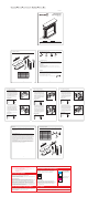
PACKAGE CONTENTS
2
3
7
C
Questions, problems, missing parts? Before returning to your retailer, call our customer
service department at 1-877-447-4768, 8:30 a.m. - 4:30 p.m., CST, Monday - Friday.
ATTACH YOUR RECEIPT HERE
Serial Number
Purchase Date
A
HARDWARE CONTENTS (shown actual size)
ASSEMBLY INSTRUCTIONS
1. Insert dowels (DD) in predrilled holes on edge
of left pilaster (G). Slip left side panel (C) over
dowels (CC) so that the dowels fit into predrilled
holes in edge. Insert a bolt (AA) through a flat
washer (BB) and a lock washer (CC) and into
predrilled holes in top edge block of left side
panel (C) and top edge block of left pilaster (G).
Tighten
with Phillips screwdriver (not included).
Repeat on center and lower edge blocks.
2. Insert dowels (DD) in predrilled holes on edge
of right pilaster (H). Slip right side panel (D) over
dowels (CC) so that the dowels fit into predrilled
holes in edge. Insert a bolt (AA) through a flat
washer (BB) and a lock washer (CC) and into
predrilled holes in top edge block of right side
panel (D) and top edge block of right pilaster (H).
Tighten
with Phillips screwdriver (not included).
Repeat on center and lower edge blocks.
1
2
G
ITEM #0000000
MODEL #28-03-66
CHESTNUT MANTEL
FOR 28 IN. FIREBOX
Français p. 9
Español p. 17
B
C
D
E
PART DESCRIPTION QUANTITY
A Top Panel 1
B Base 1
C Left Side Panel 1
D Right Side Panel 1
E Upper Front Panel 1
F Lower Front Panel 1
G Left Pilaster 1
H Right Pilaster 1
Bolt
Qty. 22
AA
BB
Flat Washer
Qty. 22
CC
Dowel
Qty. 18
SAFETY INFORMATION
PREPARATION
Please read and understand this entire manual before attempting to assemble, operate or install
the product.
WARNING
• Mantel is heavy and should be assembled near its desired location.
• It is recommended that two people move the finished mantel to prevent injury.
Before beginning assembly of product, make sure all parts are present. Compare parts with
package contents list and hardware contents list. If any part is missing or damaged, do not
attempt to assemble the product.
Estimated Assembly Time: 30 minutes
Tools Required for Assembly: Phillips screwdriver (not included).
BB
CC
Hardware Used
x 3
AA
x 3
BB
x 3
CC
DD
ONE YEAR LIMITED WARRANTY
If within one year from the date of original purchase this item fails due to a defect in material or
workmanship, we will replace or repair at our option, free of charge. To order parts or to obtain warranty
service, call 1-877-447-4768, Monday – Friday, 8:30 a.m. – 4:30 p.m., CST. This warranty does not
cover defects resulting from improper or abnormal use, misuse, accident, or alteration. Failure to follow
all instructions in the owner’s manual will also void this warranty. The manufacturer will not be liable for
incidental or consequential damages. Some states do not allow the exclusion or limitation of incidental or
consequential damages, so the above limitation or exclusion of incidental or consequential damages may
not apply to you. This warranty gives you specific legal rights, and you may also have other rights which
vary from state to state.
Variations in actual wood color and finishes which may result from natural characteristics of the wood,
such as grain patterns, mineral streaks and the like, are not considered defects. As wood continues to
move and age you may notice these slight differences in color, even on different parts of any individual
unit. Sound knots and slight surface cracks are true personality of a quality piece of wood furniture.
CARE AND MAINTENANCE
• To maintain the finish, clean with a soft, slightly damp cloth and buff with a dry cloth.
• Wood furniture should never be dragged across a floor. The added stress from dragging the unit
may cause the dragged edge to splinter or it may cause a joint to loosen.
ASSEMBLY INSTRUCTIONS
3. Set base (B) on a flat, level surface. Insert
two dowels (DD) into predrilled holes in top of
base (B). Slip left side panel/pilaster (C&G)
over dowels (DD) so that the dowels fit into
predrilled holes in bottom edge.
Insert two
bolts (AA) through flat washers (BB), lock
washers (CC) and into predrilled holes in
base (B)
. NOTE: Tighten bolts halfway with
Phillips screwdriver (not included) to allow
enough slack for Step 4.
Repeat on opposite side.
3
B
CC
BB
AA
Bolt
Flat Washer
Lock Washer
Hardware Used
x 3
AA
x 3
BB
x 3
CC
Bolt
Flat Washer
AA
BB
CC
D
Hardware Used
x 4
AA
x 4
BB
x 4
DD
Bolt
Flat Washer
Dowel
W armi ng Y our Hom e. Wa rming Y o ur H ear t.
Lock Washer
Qty. 22
DD
F
G
H
Lock Washer
Lock Washer
x 4
CC
REPLACEMENT PARTS LIST
For replacement parts, call our customer service department at at 1-877-447-4768, 8:30 a.m. - 4:30 p.m.,
CST, Monday - Friday.
8
PART DESCRIPTION PART #
A Top Panel 20-12-166
B Base 20-12-167
C Left Side Panel 20-12-168
D Right Side Panel 20-12-169
E Upper Front Panel 20-12-170
F Lower Front Panel 20-12-171
G Left Pilaster 20-12-172
H Right Pilaster 20-12-173
AA Bolt 20-12-174
BB Flat Washer 20-12-175
CC Lock Washer 20-12-176
DD Dowel 20-12-177
Printed in China
20-10-127
AA
BB
CC
A
B
C
D
E
F
G
H
DD
4. Insert dowels into predrilled holes in left and
right edges of pilasters (G&H). Slip upper
front panel (E) over dowels (DD) so that the
dowels fit into predrilled holes in side edges of
upper front panel (E). Securely tighten bolts
from Step 3 with
Phillips screwdriver (not
included).
I
nsert a bolt (AA) through a flat
washer (BB), a lock washer (CC) and into
predrilled holes in the edge block of the left
side pilaster (H). Tighten with Phillips
screwdriver (not included).
Repeat on opposite side.
4
Hardware Used
x 2
AA
x 2
BB
x 2
CC
Bolt
Flat Washer
AA
BB
CC
E
Lock Washer
ASSEMBLY INSTRUCTIONS
5. Insert two dowels (DD) into predrilled holes on
bottom edge of lower front panel (F). Slip lower
front panel (F) behind upper front panel (E) so
that the dowels fit into predrilled holes as
illustrated. I
nsert four bolts (AA) through flat
washers (BB), lock washers (CC) and into
predrilled holes in the back side of
upper front
panel (E) and assembled side panels
. Tighten
with Phillips screwdriver (not included).
5
E
CC
BB
AA
Hardware Used
x 4
AA
x 4
BB
x 4
DD
Bolt
Flat Washer
Dowel
Lock Washer
x 4
CC
6. Insert dowels (DD) into predrilled holes on
each end of top edge of assembly. Slip top
panel (A) over dowels (DD) so that the dowels
fit into predrilled holes in bottom edge.
Insert
two bolts (AA) through flat washers (BB), lock
washers (CC) and into predrilled holes in
top
panel (A). Tighten with Phillips screwdriver
(not included).
6
Hardware Used
x 6
AA
x 6
BB
x 6
CC
Bolt
Flat Washer
AA
BB
CC
DD
Lock Washer
H
DD
G
C
F
G
H
x 2
DD
Dowel
x 2
DD
Dowel
x 4
DD
Dowel
DD
DD
x 2
DD
Dowel
DD
AA
100%
BLACK
FONT & SOFTWARE USAGE STATEMENT
COLOR USAGE & PRINT REQUIREMENTS
ALL INSTRUCTION MANUALS AND RELATED MATERIAL CREATED THROUGH
ADAPTATION OF THESE TEMPLATES MUST BE APPROVED BY LOWE’S
BRAND PACKAGING DEPARTMENT PRIOR TO PRODUCTION.
CONTACT: BRAND PACKAGING DEPARTMENT, LOWE’S COMPANIES, INC.
ATTN: PACKAGING STANDARDS
1000 LOWE’S BOULEVARD, MAIL STOP: 4WTD
MOORESVILLE, NC 28117
704-758-2785
DO NOT USE ANY COLOR GRAPHICS OR PHOTOGRAPHY IN YOUR INSTRUCTION
MANUALS. INSTRUCTION MANUALS PRINT IN GREYSCALE ONLY.
ALL GRAPHICS SHOWN ARE FOR SIZE AND POSITION ONLY; FINAL LINE-ART GRAPHICS
ARE REQUIRED FOR RELEASE TO PRESS.
IMPORTANT VENDOR NOTE
VENDORS ARE RESPONSIBLE FOR THE EXECUTION AND ACCURACY OF THEIR
INSTRUCTION MANUALS. THEY ARE SOLELY RESPONSIBLE FOR INSERTING ALL OF THE
CORRECT LEGAL CERTIFICATION, WARNING, WARRANTY, AND OTHER APPLICABLE
PRODUCT INFORMATION. HARDWARE MUST BE SHOWN AS ACTUAL SIZE IN THE
HARDWARE CONTENTS SECTION WITH LINE ART DRAWING OF THE HARDWARE, THE
DIMENSIONS, NAME DESCRIPTOR AND QUANTITY. LOWE’S IS NOT RESPONSIBLE FOR
ANY INCURRED DESIGN, TRANSLATION OR PRINTING COSTS. PLEASE REFER TO THE
TRANSLATION REQUIREMENTS ON LOWESLINK.COM
• FONTS USED ON THIS FILE: SEE FONT LEGEND.
• CONTACT YOUR APPROPRIATE FONT VENDOR TO PURCHASE THE REQUIRED FONTS
FOR THIS PACKAGE LINE.
• ADOBE ILLUSTRATOR CS3 WAS USED TO CREATE THIS FILE.
LOWE’S REQUIRES EACH VENDOR TO OBTAIN THEIR OWN LINE-ART GRAPHICS. ALL INSTRUCTION MANUAL GRAPHICS WILL
BE APPROVED BY LOWE’S BRAND MANAGEMENT DURING PROOFING.
THIS DESIGN IS PROPRIETARY AND CONFIDENTIAL TO LOWE’S COMPANIES, INC. AND CANNOT BE COPIED OR OTHERWISE
REPRODUCED OR USED WITHOUT THE EXPRESS WRITTEN PERMISSION OF LOWE’S.
THESE ARE THE PANTONE COLORS THAT ARE USED IN THIS FILE.
THESE MUST BE USED WHEN CREATING ANY OTHER PACKAGING.
THE ADDITION OF OTHER SPOT COLORS IS NOT PERMITTED.
ARTWORK DISCLAIMERS
FONT LEGEND
ALL FONTS MUST BE ARIAL BOLD OR ARIAL REGULAR, 12 PT. (MINIMUM) ON 14 PT. LEADING UNLESS OTHERWISE SPECIFIED.
REQUIRED PAPER TYPE
USE THE FOLLOWING PAPER FOR YOUR INSTRUCTION MANUALS:
• PAPER BASIS WEIGHT: 20-lb. PAPER OR 75 GRAMS/SQ METER
• DOCUMENT SIZE: PRINTED TWO-SIDES ON TABLOID OR A3 AND FOLDS
TO LETTER SIZE OR A4. INCLUDE SAMPLE MOCK-UP TO INDICATE
FOLD(S) AND PAGE LAYOUT.
THIS COLOR IS USED FOR
NOTES AND DOES NOT
PRINT.
CALL OUTS
(DO NOT PRINT)
THIS COLOR INDICATES
ALL TEXT TO BE CHANGED
WITH PRODUCT SPECIFIC
TEXT.
EDITABLE TEXT
(DO NOT PRINT)