
Use and Care Manual


16
INSTALLATION
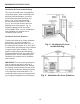
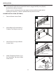
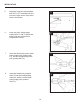
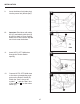
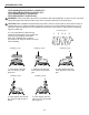
13. Push Rocker Switch (E) into
Control Panel and secure.
13
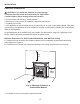
14. Check that all wires are secure
and reattach Blower Access Panel
to Outer Casing. Capture the
Green Ground wire between the
Access Plate and Outer Casing
with the upper right screw.
E
1
1
2
2
3
3
4
4
A A
B B
C C
D D
SHEET 1 OF 1
DRAWN
CHECKED
QA
MFG
APPROVED
dandowning
4/12/2013
DWG NO
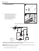
Power Cord Attachment
TITLE
SIZE
C
SCALE
REV
Green Ground
Wire
14
Screw
Outer
Casing
Access Panel
Power Cord
t
WHITE
GREEN
RED
BLACK
BLACK
AUTO OFF
MAN
1
2
3
4
5
~120V
60Hz
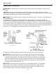
1. Power Cord
2. Bushing Strain Relief
3. Blower
4. Temperature Sensor
5. Rocker Switch
FAN
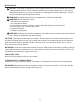
Electrical Wiring Diagram
CAUTION: Label all wires prior to disconnection when servicing controls. Wiring errors can
cause improper and dangerous operation.
Verify proper operation after servicing.
NOTE: If any of the original wire as supplied with the appliance must be replaced, it must be
replaced with a wire of at least an equal temperature rating.