
Installation Guide


15
INSTALLATION
WARNING: Failure to position the parts in accordance with these diagrams or failure to
use only parts specically approved with this heater may result in property damage or
personal injury.
Before beginning assembly or operation of the product, make sure all parts are present.
Compare parts with package contents list. If any part is missing or damaged, do not attempt
to assemble, install or operate the product. Contact customer service for replacement parts.
Estimated Assembly Time: 1 to 2 hours
Tools Required for Assembly (Not Included, unless otherwise stated):
Before installing heater, make sure you have the the following:
• Hardware package (provided with heater)
• Approved exible gas hose if allowed by local codes
• Sealant (resistant to natural or propane/LP gas)
• Electric drill with 3/16- in. drill bit
• Phillips screwdriver
• External regulator (supplied by installer if required)
• Piping (check local codes)
• Equipment shuto valve
• Test gauge connection
• Sediment trap
• Tee joint
• Pipe wrench
• 3/8" NPT to 1/2" are tting
• Allen Wrench
UNPACKING
1. Remove logs, grate, and burner base assembly from carton. NOTE: Do not pick up burner base
assembly by burners as this could damage heater. Always handle base assembly by frame.
2. Remove all protective packaging applied to logs and heater for shipment.
3. Check all items for any shipping damage. If damaged, promptly inform dealer where you
purchased the heater.
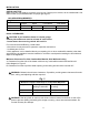
Attachment Screws
(2) Pieces
GRATE ASSEMBLY PROCEDURE
1. Position the grate in front of the burner
so the 2 legs are pointing downward, the
"grate ends" that the logs sit on are point-
ing upward, and the screw holes line up
with the screw holes on the burner unit
(See Fig. 11)
2. Hand tighten the grate to the burner with
(2) Attachment Screws, each at an equal
distance until hand tightening is no
longer possible.
3. Finish tightening each Attachment Screw
with a screw driver, but make sure not to
over tighten.
Fig. 11
Grate