
Full Product Manual


8
INSTALLATION
INSTALLATION
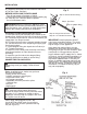
PREPARE DAMPER
The chimney damper must be xed open in a man-
ner which will maintain the minimum permanent
vent opening at all times. This may be accom-
plished by installing a screw or bolt in the edge of
the damper to prevent the damper from closing, by
drilling a hole or holes in the damper blade or by
installing the supplied damper clamp on the edge
of the damper blade (see Figure 2).
NOTE: The State of Massachusetts requires the
chimney damper to be removed or to be welded in
the fully open position.
HEARTH KIT ASSEMBLY
Note: The following instructions apply to
dual ame "U" style burners. Be sure all pipe
threaded connections are tight, and have
thread compound to prevent leaks.
1. Determine which side the gas line will be
coming into the replace.
Gas line is on the right side. This unit
is manufactured with the gas inlet on the
right side of the burner pan. See Installation
and Gas Connection, page 9.
Gas line is on the left side. If your gas
line will be coming into the replace from
the left side, continue with step 2.
2. Using a screwdriver, remove cover plate
on left side of burner pan (see Figure 3).
3. Unscrew burner inlet tting from burner
manifold (see Figure 3).
4. Place burner manifold in pan with threaded
opening facing opening on left side.
5. Using thread sealant (resistant to the action
of natural gas) on larger end of tting,
screw the burner inlet tting through hole
and into burner manifold. Tighten using a
wrench (see Figure 4).
6. Using burner clamp, screw, and nut provided,
assemble clamp to pan. This will hold the burner
manifold in place (see Figure 4).
7. Using screws removed in step 2, install
cover plate over opening on right side of
burner pan (see Figure 4).
Fig. 3
Fig. 4
Fig. 2
Damper
"Opened Position"
Damper Clamp
Damper