
Integrated Amplifier Instruction Manual 9200


8
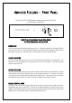
CD XLR INPUT TERMINALS
Below the CD RCA inputs are an additional set of ‘line level’ XLR balanced inputs for use with source
components that feature XLR balanced outputs. Balanced signals are carried via a three way cable.
The XLR pin configuration used in all Plinius product is:
PIN 1 to GND
PIN 2 to +Signal
PIN 3 to -Signal
NOTE: Because of the way our XLR and balanced inputs are configured it is not possible to connect both
XLR and RCA at the same time.
INPUT SELECTION SWITCH
This switch directly below the ‘TAPE 1’ input is used to select the pair of CD input sockets required as
described above. Up selects the CD RCA input connections, while down selects CD XLR input.
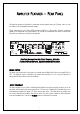
OUTPUT TERMINALS
Connections for the loudspeakers are provided on the right hand side of the rear panel. Two parallel pairs
of five way binding posts for each channel are fitted – these provide ease of use with bi-wiring and
multiple cables requiring a large contact area.
TAPE OUTPUTS
These RCA outputs are situated next to the tape RCA inputs, and are provided to interface to a pair of line
level recording devices. The position of the record selector on the front panel determines from which
device a recording is being made. As these tape outputs are always ‘live’, both can be used to record the
chosen signal at any time.
MUTE SWITCH
The mute switch enables disconnection of the output, without the need to use the remote control. When
the amplifier is in mute, the LED on the front panel will dim.