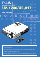
DATA PROJECTOR U2-1200/U2-817 E S S User’s Manual O T U A R E W O S P U T A T S R E W O P E C R U O S U N E M - S E LE C T ENTER + A C C CANCEL RG DV B I VO L KSTN R CA ER TIM NC EL ZO OM TE EN AU TO MENU T AS PE C K QU IC VID EO O S-V IDE EC O RG B MU TE I DV FR EE ZE OFF PO WE R ON IMPORTANT * DLP™ (Digital Light Processing) and DMD (Digital Micromirror Device) are registered trademarks of Texas Instruments Incorporated (U.S.A.).
IMPORTANT SAFETY INFORMATION Precautions Please read this manual carefully before using your PLUS U2-1200/U2-817 Data Projector and keep the manual handy for future reference. CAUTION TO PREVENT SHOCK, DO NOT OPEN THE CABINET. NO USER-SERVICEABLE PARTS INSIDE. REFER SERVICING TO QUALIFIED PLUS SERVICE PERSONNEL. This symbol warns the user that uninsulated voltage within the unit may have sufficient magnitude to cause electric shock.
IMPORTANT SAFETY INFORMATION Important Safeguards These safety instructions are to ensure the long life of the unit and to prevent fire and shock. Please read them carefully and heed all warnings. Installation • • • • • • For best results, use the unit in a darkened room. Place the unit on a flat, level surface in a dry area away from dust and moisture. Do not place the unit in direct sunlight, near heaters or heat radiating appliances.
Major Features Book-sized, lightweight (at about 2.5 kg/5.5 lb) high-intensity mobile projector The synergy of the DLP™ (Digital Light Processing) display system and our own optical design serve to improve the optical utilization efficiency. The three primary colors (RGB) required in color expression are reproduced with one DMD (Digital Micromirror Device of high precision). These factors have enabled a design that offers both high intensity and small size/ lightweight features.
Table of Contents IMPORTANT SAFETY INFORMATION ................................................................................... E-2 Major Features ....................................................................................................................... E-4 Table of Contents ................................................................................................................... E-5 Checking the Supplied Accessories ..................................................................
Table of Contents Color ...................................................................................................................................... Gamma ..................................................................................................................... Color Temp. ............................................................................................................... White ...................................................................................................
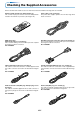
Checking the Supplied Accessories Remove the main unit and the accessories from the box and check that the following items are included. Power cable (1.8 m / 5.9 feet) [1] This power cable supplies power to the unit. See Page E-23 about connections. V O L Remote control (includes one button battery) [1] This controls the projector. Please remove the transportation insulation sheet at time of purchase. (See Page E-12.
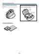
Checking the Supplied Accessories Carrying case (for projector and accessories) [1] This is a case designed for storing the projector and its accessories. Use this carrying case when storing or moving the projector. HOW TO PUT THE PROJECTOR INTO THE CARRYING CASE Attach the lens cap to the projector before putting the projector into the carrying case, and then fasten the velcro strap. Put accessories into the pocket.
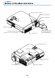
Names of the Main Unit Parts Remote control sensor [E-12] Zoom ring [E-26] C C ENTER A E S S - Focus ring [E-27] S CANCEL E LE C T M + E U U A N T O S T A T O S P U W E O R S U R C E P Lens O W E R Ventilation slots Front adjuster button [E-27] (There is also one on the right side.) Exhaust vents Lens cap To protect the lens, attach the lens cap when the projector is not being used.
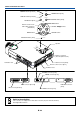
Names of the Main Unit Parts POWER indicator [E-23,59] POWER POWER POWER button [E-23] STATUS STATUS indicator [E-23,59] AUTO SOURCE SOURCE button [E-28] AUTO button [E-28] MENU MENU button Buttons used in menu and toolbar operations [E-24,34,35] SELECT ▲▼ buttons SELECT ENTER button EN CANCEL button EL TE NC R CA ACCESS indicator [E-12] ACCESS Speaker R WE PO CE UR R WE PO US AT ST SO TO AU NU ME + CT CANCEL LE SE - SS ENTER CE AC RG BO Built-in security slot (Se
Names of the Remote Control Parts N T A U TO ER TIM R E T N E EL NC CA M O ZO KST C NU K Q FR E E P ZE O W D E V I R M V U ID TE E O O R FF G U B IC S E -V C O ID E O A S P E ME O N Infrared transmitter [E-12] POWER button [E-23,25] FREEZE button [E-30] (Freezes moving pictures) MUTE button [E-30] (Temporarily cancels the video and audio) ON POWER OFF FREEZE MUTE ECO DVI RGB VIDEO S-VIDEO QUICK ASPECT Buttons used for input selection [E-2
Preparing the Remote Control Button Battery Replacement Using the remote control for the first time The battery compartment is fitted with a transportation insulation sheet at the time of shipping. Pull out the sheet and remove it. The remote control is now ready for use.
The Procedure Up to Projecting to the Screen Perform setup adjustments in the following order. 1 Position the projector Determine the locations to set up the screen and the projector. See "Placement Guide" on Page E-14, 15. 2 Connect the video equipment and personal computer Connect your equipment to the projector. When making connections with the personal computer's DVI connector or RGB connector, see "Connections with Personal Computers" on Page E-16.
Placement Guide * Use this information as a guide to find out about the screen size when the projector is placed at a certain location, or to find out the approximate size of a screen that will be required. * The projection distance (from the lens surface of the projector) within which focusing can be maintained is 1.20m / 3.94 feet to 13.81m/45.3 feet (for the U2-1200) and 1.20 m/3.94 feet to 17.70m/58.1 feet (for the U2-817). Please set up the projector within this range.
Placement Guide U2-817 Screen Size and Projection Distance Center of lens m (feet) 7 (23.0) 300" WIDE 5 (16.4) 200" 4 (13.1) 150" 3 (9.8) 120" 100" h1 2 (6.6) 80" 60" 21-26" Screen Height 6 (19.7) 250" TELE h2 40" 1 (3.3) h2 0 0 1 Center of(3.3) lens 2 (6.6) 3 (9.8) 4 (13.1) 5 (16.4) 6 (19.7) 7 (23.0) 8 (26.2) 9 (29.5) 10 (32.8) 11 (36.1) 12 (39.4) 13 (42.7) 14 (45.9) 15 (49.2) 16 (52.5) 18 m (59.
Connecting Personal Computers and Video Equipment Connecting this unit with a personal computer permits presentation data to be projected as a large screen display at conferences, lectures, and on other occasions. Furthermore, connecting this unit to a DVD player or other video equipment source in combination with an audio/video amplifier and speaker system will allow you to enjoy convincing home theater.
Connecting Personal Computers and Video Equipment Personal Computers with a Mini D-Sub 15-Pin Connector • • When connections are made to the RGB connector of this projector, make these connections using the supplied RGB signal cable. Please orient the connector to mate properly when before inserting it, then turn the screw knobs to secure the connector to that of the projector.
Connecting Personal Computers and Video Equipment To Output the External Output Signal of a Notebook Computer When projection will be with a notebook computer connected, knowledge will be required for the cable connection and notebook computer startup procedure as well as the operation that follows notebook startup. Please consult the instruction manual of your notebook computer or the on-line help while performing the following procedure.
Connecting Personal Computers and Video Equipment Connections with Composite Signals Video Equipment with VIDEO Connectors • Make the connection to the VIDEO connector of the projector using the supplied video cable. • The input setting of the VIDEO connector has been set to "Auto" at the factory; however, if the projector does not project, please change the input setting to "Your Country's Television Broadcast System" using the menu sequence of [Setup] → [Input Format] → [Video].
Connecting Personal Computers and Video Equipment Connections with Component Signals When the Video Equipment Has a YCbCr Connector or YPbPr Connector • Make connections to the RGB connector of the projector using a component cable, which is available separately. • The projector has been set to "Auto" at the factory; however, if it does not project, please change the input setting to "Component" using the menu sequence of [Setup] → [Input Format] → [RGB]. See "Input Format" on Page E-49.
Connecting Personal Computers and Video Equipment Connections with the AUDIO Jack * Make the connection to the projector's AUDIO jack using the supplied audio cable. When the audio jack of the equipment that is to be connected is of the RCA phono type, make connection via the supplied audio conversion cable. * The built-in speaker of the projector provides monaural audio. To enjoy convincing audio reproduction, please connect the audio output of the video equipment to your audio system.
Connecting Personal Computers and Video Equipment Connections with the RGB OUT Connector • The screen of the personal computer that is connected to the RGB connector will be output. • While controlling the personal computer in front of you, the same screen can be projected with the projector. This allows personal computer control even from a position at which the projector image cannot be viewed.
Power Cable Connections and Switching the Power On/Off There is an order in which the power cable is connected and the power is switched on/off. Operating 1 Connect the AC IN connector of the projector and the power outlet using the supplied power cable. The POWER indicator will light in amber, and the unit will enter the standby mode. Lit amber PO W WE POWER R ST AT SO US AU UR To wall outlet CE STATUS TO M U EN + CT LE SE - Firmly plug in all the way.
Power Cable Connections and Switching the Power On/Off When [Menu Language Select] is Displayed Upon Switching On the Power The first time the power is switched on after purchase, [Menu Language Select] will be displayed. Follow the procedure described below and select the display language of the projector. If the image is blurred, turn the focus ring counterclockwise or clockwise to focus it. See Page E-27.
Power Cable Connections and Switching the Power On/Off Finishing 1 Switch off the power of the connected equipment 2 Switch off the power of the projector Main unit operation: Press and hold the POWER button for a while. Remote control operation: Press the POWER OFF button. ON POWER OFF Power Off OK ? The [Power Off] display appears. When the level gauge reaches maximum, the projection screen will go off (in about 5 seconds) and the projector will enter the power-off operation.
Adjustment of the Projection Screen Switch on the power of the connected equipment and make the adjustments with the video signal being input to the projector. Adjustment of the Projection Screen 1 Turn the zoom ring and adjust the size of the screen. Perform the setting adjustments using the projection distance table of the "Placement Guide" as your guide. Zoom ring Smaller screen Larger screen 2 Adjust the projection image to the screen. Check that the screen is set level and vertically.
Adjustment of the Projection Screen 3 Turn the focus ring and adjust the focus of the screen Focus ring Making Adjustments with the Adjusters SS CE CANCEL AC ENTER + CT LE SE - MEN U SO UR CE AU TO PO WER PO WER ST AT US Raising the projection image While viewing the projection image, (1) press and hold the front adjuster buttons located at the left and right and, (2) raise the projector to align the image with the screen, then release your fingers.
General Operation This section describes the use of direct operation with the main unit or remote control buttons. For information about operation using the menu, see "Menu Operation Method" on Page E-35 and the various items on Pages E-42 to E-56. Input Selection This operation selects the input signal to be projected. POWER Main unit operation: Press the SOURCE button. (It will not function while the menu or the quick menu is displayed.
General Operation Selection of Aspect Ratio This function selects horizontal and vertical picture proportions of the input signal. Press the ASPECT button while viewing the projected image and select the aspect ratio. Personal Computer Signal Each press of the ASPECT button advances the selection one step in the sequence of Auto → Direct → Real, and then repeats. Auto ............ Automatically enlarges or reduces the image to project a full screen in a ratio of 4:3 Direct ..........
General Operation Freezing a Moving Picture This function is used to stop and view a moving picture. Note that the input image continues to advance even though the picture there is a still picture condition. A press of the FREEZE button changes the screen to a still picture. A further press returns the screen to a moving picture.
General Operation Using the Presentation Timer The presentation is given while checking the timer displayed on the screen. The gauge display allows the remaining time to be known at a glance. (3) (1) Press the TIMER button to show the settings display. The display will close when an operation has not been made for about 10 seconds. CAN U CEL MEN ENTER Presentation Timer Off (1) TIME R KSTN ZOOM VOL [Timer settings display] Press the CANCEL button to close the display immediately.
General Operation Keystone (3) Use this to adjust for trapezoidal (keystone) distortion of the projected image. Adjustment Method (1) Press the KSTN button. The keystone adjustment display will appear. CAN U CEL MEN ENTER Keystone 0 TIME R KSTN ZOOM VOL (2) Press the "+" / "-" button while viewing the screen to set the left and right sides parallel. (1) Press the “–” button. Press the “+” button. (2) The dotted lines indicate the proper condition.
General Operation Enlargement of the Image and Video Movement This function digitally enlarges the personal computer image and video image (up to 10 times). (3) (1) Press the ZOOM button. The zoom selection display will appear. CAN U CEL MEN Zoom (4) 0 ENTER (2) Enlarge to the desired size. Each press of the (+) button enlarges the image and each press of the (-) button makes the image smaller (returning it to 1:1).
General Operation Using the Quick Menu (1) This function permits frequently used adjustments to be performed quickly. Note that the Quick Menu will not be displayed unless the signal of the connected equipment is input. Please select the input that you wish to adjust. MENU Main unit operation (1) Press the SELECT 왖 or 왔 button to display the quick adjustment display. Make further presses to switch to the desired adjustment display. SELECT (2) (2) Press the SELECT 왗 or 왘 button to adjust.
Menu Operation Method • This section describes only the menu operation method. Please see this item should you need information while performing menu operations. • For information about a menu function, adjustment, or setting, please see one of the pages containing such descriptions. • Adjustments and settings are made by projecting an image and adjusting to an optimum condition. • The remote control should be pointed toward the remote control sensor of the projector and operated.
Menu Operation Method Menu Screen Names and Functions Menu Name This is the title of the menu. There is a change to the title screen when the menu is selected. The selected menu name appears in red. Image Cursor (Deep Blue) This permits setting/adjustment of the item located at the cursor position. Color View Setup Auto Source On Auto Power Off Off Info. Menu Potision Lamp Mode Normal Input Format Image Off Presentation Timer Item Name This is the name of the adjustment or setting.
Menu Operation Method Performing Menu Operations • When a signal is not being input, only [Setup] and [Info.] can be selected. • The menu display will close if, after pressing a button, the next button operation is not made within 30 seconds. • The adjustment and the setting values are stored even when the power is switched off or the plug is disconnected from the power outlet. (Note that some items are not stored.
Menu Operation Method Displaying the Cursor 3 Press the SELECT 왔 button to display the cursor Image CAN U CEL MEN Color View Setup Aspect 3 Filter ENTER Off Vertical Flip TIME KSTN R This condition allows selection of the item name. Info.
Menu Operation Method Closing the Menu 6 Press the MENU button and close the menu display CAN U CEL MEN ENTER TIME KSTN R Selecting Another Menu Name with Remote Control Operation When a sub menu is displayed, press the CANCEL button and close the sub menu. Press the CANCEL button again and cancel the cursor display.
Menu Operation Method List of Item Names Offering Input Selection and Adjustments/Settings The item names that can be adjusted/set will differ depending on the input signal. [Example of Menu Display Items at the Time of Input Signal Analog RGB Selection] Image Brightness Contrast Picture Adj. Fine Picture H Position V Position Color View Setup Info.
Menu Operation Method Image Color View Setup Auto Source On Auto Power Off Off Info.
Picture • Perform this operation while projecting the picture for which the adjustment/setting will be made. • Select the menu name "Picture". See "Menu Operation Method" on Page E-35 for information about performing menu operations. The item name display will differ depending on the input signal. See "List of Item Names Offering Input Selection and Adjustments/Settings" on Page E-40.
Picture Fine Picture Adjust this when the picture shows a lack of color fidelity or flickering. Select the "Fine Picture" item name and adjust with the SELECT 왗왘 buttons so that the lack of color fidelity or the flickering disappears. H Position Adjust this when the picture is shifted to the left or right. Select the "H Position" item name and adjust with the SELECT 왗왘 buttons. V Position Adjust this when the picture is shifted up or down.
Color • Do the following operation while displaying the image you want to adjust or set. • Select the menu name "Color". See "Menu Operation Method" on Page E-35 for information about performing menu operations. The item name display will differ depending on the input signal. See "List of Item Names Offering Input Selection and Adjustments/Settings" on Pages E40. Gamma Gamma corrects the proportion of change of the dark portions from the bright portions of the input signal.
Color Color Space Set this function when a component signal (YCbCr or YPbPr) is projected and the image is extremely red or extremely green. Gamma Normal Color Temp. Normal Select the item name "Color Space" and use the SELECT 왗왘 buttons to select a color space setting that provides a normal image.
View • Perform this operation while projecting the picture for which the adjustment/setting will be made. • Select the menu name "View". See "Menu Operation Method" on Page E-35 for information about performing menu operations. The item name display will differ depending on the input signal. See "List of Item Names Offering Input Selection and Adjustments/Settings" on Page E-40. Aspect This function sets the horizontal and vertical picture proportions of the input signal.
View Vertical Flip In selecting the method of projecting to the screen, these functions are set when the projector is in a suspended or a rear screen installation. Aspect Select the item name “Vertical Flip” or “Horizontal Flip” and select the setting contents with the SELECT 왗왘 buttons. Vertical Flip In a suspended installation, set “Vertical Flip” On and “Horizontal Flip” On.
Setup • Select menu name "Setup". See "Menu Operation Method" on Page E-35 for information about performing menu operations. The item name display will differ depending on the input signal. See "List of Item Names Offering Input Selection and Adjustments/Settings" on Page E-41. Auto Source The Auto Source function automatically detects the input signal when the power supply is switched on and when the input is switched.
Setup Lamp Mode Use this if the picture is projected on a small screen and the picture is too bright or when projecting images in dark rooms. Auto Source On Auto Power Off Off Select the item name “Lamp Mode” and select the setting contents with the SELECT 왗왘 buttons. Memu Position Eco ............. The lamp brightness is set to 80% and the lamp life is extended. (STATUS indicator is green) Normal ....... The lamp brightness is set to 100% and the screen is bright.
Setup Presentation Timer The presentation is given while checking the timer displayed on the screen. The gauge display allows the remaining time to be known at a glance. Auto Source On Auto Power Off Off Memu Position Select the item name “Presentation Timer” and select the setting contents with the SELECT 왗왘 buttons.
Setup Logo Position This is the setting of the position for the display of the logo. Changes cannot be made after the capture. See "Startup Logo Creation" on Page E-57 for information about using logo capture. Logo Background Red Green Blue Select item name “Logo Capture”, press the ENTER button, and the sub menu will open. Select “Logo Position” and select the display position icon with the SELECT 왗왘 buttons.
Setup Start Logo Capture This executes image capture. See "Startup Logo Creation" on Page E-57 for information about using logo capture. Logo Background Green Select item name “Logo Capture”, press the ENTER button, and the sub menu will open. Select “Start Logo Capture” and press the ENTER button. There is a change to the capture range selection display. Black 0 0 0 Red Blue Logo Scaling Real Logo Position Caputure mode Note: Selection is not possible in the absence of a signal.
Setup Language This function sets the language that is displayed on screen in the messages and menu displays. Auto Source On Auto Power Off Off Select item name “Options” and press the ENTER button to open the Options sub menu. Select item name “Language” and press the ENTER button to open the Language sub menu. Select the language with the SELECT 왖왔 buttons.
Setup Startup Screen This is the selection of whether or not to display the logo screen at startup time. See "Startup Logo Creation" on Page E-57 for information about using logo capture. Select item name “Options” and press the ENTER button to open the Options sub menu. Select item name “On Screen” and select the setting contents with the SELECT 왗왘 buttons.
Info. • Select menu name "Info.". See "Menu Operation Method" on Page E-35 for information about performing menu operations. The item name display will differ depending on the input signal. See "List of Item Names Offering Input Selection and Adjustments/Settings" on Page E-41. Status This displays information about the equipment. Status Factory Default Select item name “Status” and press the ENTER button. There is a change to the status display. Press the CANCEL button to return to the menu.
Info. Resolution / Frequency This function displays the resolution and frequency of the detected input signal. Status Factory Default When an analog RGB, DVI analog, or DVI digital signal is input, there will not be a display unless input selection of RGB or DVI has already been made. Lamp Timer Reset Resolution 1024×768 Frequency 75Hz 60kHz Lamp Timer 12h Lamp Timer This displays the lamp timer. Status This projector has an Eco mode function.
Startup Logo Creation The startup logo is a function that displays a created logo. After turning on the power, a logo appears in about 15 seconds. The displayed logo disappears in about 30 seconds. A logo can be displayed by creating it on a personal computer, then projecting it with this projector and capturing it. See Pages E-50 to E-52 for information about the selection of “Logo Capture” and an explanation of the items. Preparation and Projection of the Image 1.
Startup Logo Creation 7. Start Capture → Page E-52 Selection will not be possible unless a signal is being input. Pressing the ENTER button will start the capture. (1) While capture is operating, “Capturing Logo” is displayed and the advancement of the gauge is displayed. (2) When the capture is completed, “Logo Capture Complete” is displayed for about 10 seconds. (3) When a logo capture has already been saved, it will be overwritten.
When an Indicator is Lit or Flashing PO PO R WE ST AT WE R SO US A UR CE O UT ME NU + LE SE CT - CANCEL The indicators on the projector’s control panel light or flash to notify of problems, as described below. An indicator is also used to notify you of the currently set power mode (under normal circumstances). See “Power Cable Connections and Switching the Power On/Off” on page E-23.
Troubleshooting Check the following matters before requesting servicing. Problem Power does not turn on Reference Page Check • Is the power cord plugged into a power outlet? • Is the lamp cover properly mounted? • Is the projector’s temperature high? To protect the projector, the power cannot be turned on when the projector’s temperature is abnormally high.
Cleaning • Be certain to disconnect the power plug from the power outlet before cleaning. • Do not spray or otherwise expose the projector, lens, or screen to volatile substances such as insecticides. Do not leave rubber or vinyl products in contact with the projector for long periods. Doing so could cause them to undergo qualitative changes or the coatings may peel, etc. Cleaning a Soiled Projector Main Unit • Wipe with a lint-free, soft, dry cloth.
Replacing the Lamp Cartridge • The lamp that is used as a light source in the projector has a limited service life. The rated service life of the lamp is about 3000 hours (when used in normal mode only). This could be shortened depending on conditions of use and other factors. Note that lamp life will be extended when the projector is often used in Eco mode.
Replacing the Lamp Cartridge Preparations: Turning the projector upside-down on top of a soft cloth, etc., so that it does not get scratched makes it easier to replace the lamp cartridge. Turn the projector right-side up after replacing the lamp cartridge. 1 Unplug the power cord. 2 Turn the projector upside-down. 3 Remove the lamp cover. (1) Turn the lamp cover’s set screw counterclockwise and loosen until the screw turns freely. (The screw does not come off.
Replacing the Lamp Cartridge 5 Mount the new lamp cartridge. (1) Placing the lamp cartridge with its socket facing towards you, slowly press the lamp cartridge in. (Line it up with the screw holes in the projector.) (2) Turn the two lamp cartridge screws clockwise to tighten them. 6 Mount the lamp cover. (1) Set the tip of the lamp cover in place, then close the lamp cover. (2) Turn the lamp cover’s screw clockwise to tighten it. 7 Reset the Lamp Timer.
Specifications Model U2-1200/U2-817 Optical Method of projection : DMD Lamp Projection lens : Image size Light Output Contrast Ratio DLP™ (single chip DMD) U2-1200: 0.7 inches 1024 768 dots U2-817: 0.55 inches 800 600 dots 200 W ultra-high pressure mercury lamp Manual zoom ( 1.2), manual focus, F = 2.4 to 2.6, f = 26.5 to 31.8 mm U2-1200: Minimum 27 inches (projection distance: 1.2 meters, tele mode) Maximum 300 inches (projection distance: 11.
Table of Supported Frequency The projector automatically identifies the signal input from the computer and selects the optimum resolution as shown on the table below. Manual adjustments may be required for some input signals. See “Picture Adj. / Fine Picture / H Position / V Position” on page E42, 43.
E-67 Unit: mm (inch) 58 (2.3) 230 (9.0) 295 (11.