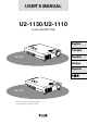
USER’S MANUAL U2-1130/U2-1110 DATA PROJECTOR English – CT SELE MENU US STAT Français POWER UP DOWN + R ENTE MOUS E RGB IN PC AU DIO S-VIDE O VIDEO L/MONAUDIO O R Deutsch U2-1130 Italiano Español MENU STAT US POWER CT SELE – UP DOWN + R ENTE MOUS E RGB IN PC AU DIO S-VIDE O VIDEO L/MONAUDIO O R U2-1110* * The U2-1130 is used for illustration purposes in this manual unless otherwise specified.
Note: This equipment has been tested and found to comply with the limits for a Class A digital device, pursuant to Part 15 of the FCC Rules. These limits are designed to provide reasonable protection against harmful interference when the equipment is operated in a commercial environment. This equipment generates, uses, and can radiate radio frequency energy and, if not installed and used in accordance with the instruction manual, may cause harmful interference to radio communications.
USER’S MANUAL U2-1130/U2-1110 English
IMPORTANT SAFETY INFORMATION Precautions Please read this manual carefully before using your PLUS U2-1130/U2-1110 Data Projector and keep the manual handy for future reference. Your serial number is located next to the main power switch on the back of the unit. Record it here: CAUTION TO PREVENT SHOCK, DO NOT OPEN THE CABINET. NO USER-SERVICEABLE PARTS INSIDE. REFER SERVICING TO QUALIFIED PLUS SERVICE PERSONNEL.
Table of contents Cleaning IMPORTANT SAFETY INFORMATION ................................... 2 • Disconnect the power cable (mains lead) from the unit. • Clean the cabinet of the unit periodically with a damp cloth. If heavily soiled, use a mild detergent. Never use strong detergents or solvents such as alcohol or thinner. • Use a blower or lens paper to clean the lens, and be careful not to scratch or mar the lens.
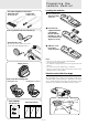
Checking the supplied accessories Basic information and preparations Features Congratulations On Your Purchase Of The U21130/U2-1110 Data Projector Make sure your box contains everything listed below. If any pieces are missing, contact your dealer. Please save the original box and packing materials in case you ever need to ship the unit. The number of accessories is indicated in brackets. The U2-1130/U2-1110 is one of the very most spectacular data projectors available today.
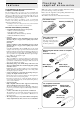
Preparing the remote control Inserting the batteries For video equipment connection S-video cable Audio video cable (1 m/3.3 ft.) [1] (1 m/3.3 ft.) [1] 1 Press firmly and slide the battery cover off. 2 Insert the two supplied batteries (size AA/R6). Ensure that the polarities (+ and –) of the batteries are aligned correctly. Lens cap (attached to the lens of the unit) [1] About the lens cap The lens cap is fixed on the bottom of the unit as shown in the illustration below.
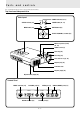
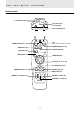
Parts and controls For operational instructions, refer to the page indicated in brackets. Top, front and side panel view Control panel STATUS POWER STATUS indicator [32] POWER indicator [15, 17] POWER button [15, 17] MENU ENTER ENTER button [23] MENU button [23] SELECT UP SELECT UP/DOWN/+/– buttons [23] DOWN Monaural speaker (1.
Rear and side panel view Remote sensor [5] STAT US POWER MENU ENTE SELE R CT UP – + DOWN Built-in security slot [see below] Ventilation slots Rear adjuster [16] Adjuster button (left) [16] AC IN terminal [15] Built-in Security Slot This security slot supports the MicroSaver® Security System. MicroSaver® is a registered trademark of Kensington Microware Inc. The logo is trademarked and owned by Kensington Microware Inc.
Parts and controls (continued) Remote control L-CLICK button [14, 23] Laser pointer [19] (Laser aperture) Infrared transmitter [5] OFF POWER VIDEO S-VIDEO ON LED Lights when any button is pressed.
I n s t a l l a t i o n The distance from the unit lens to the screen determines to the size of the projected image, therefore, you need to consider the place where you set up the unit and screen before making connections. You also need to consider the screen size and height of the unit and screen as other important factors. Tip A non-glossy wall may be used as a substitute for a screen. WARNING • Carrying the unit Always carry the unit in the carrying case.
Installation (continued) • Projecting distance and image size Projection distance 0 0 1 3.3 2 6.6 3 9.8 4 5 13.1 16.4 Tele. – Wide 250″ – 300″ 11 12 (m) 36.1 39.4 (feet) Diagonal image size (inch) Height of the projecting image 9.8m / 32.2 feet 6m / 19.7 feet 4.9m / 16.1 feet 100″ – 120″ 60″ – 72″ 8 9 10 26.2 29.5 32.8 12.3m / 40.4 feet 200″ – 240″ 80″ – 96″ 6 7 19.7 23.0 3.9m / 12.8 feet Image center in wide mode 5m / 16.4 feet Image center in telephoto mode 4m / 13.1 feet 2.
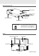
C o n n e c t i o n s Connecting video equipment You can connect up to two pieces of video equipment to the unit following the illustrations below. • You can switch the input source (picture) to VIDEO or S-VIDEO when you connect two pieces of equipment. (The S-VIDEO connection provides more vivid color and higher resolution compared to the VIDEO connection.) • You can output the sound of only one component through the unit speaker even when two components are connected.
Connecting a PC or Macintosh Connecting a PC or Macintosh to the unit will enable you to project your computer screen images for impressive presentations.
Note on the PowerBook connection Depending on the model of your PowerBook, the additional Apple video cable adapter may be required with the above connection. Monitor adapter (supplied) Video cable adapter Mini D-Sub 15-pin connector (supplied) To the Data Projector Modifying the DIP switch setting (for Macintosh) Modify the DIP switch setting according to the DIP switch setting table below.
Using the remote mouse – Wireless control as a computer mouse function The supplied remote control enables you to operate the computer’s mouse functions by connecting the computer to the MOUSE connector of the unit. It is a great way to control your computer-generated presentations. How does the remote control operate the computer? • The cursor key on the remote control operates the computer mouse functions.
O p e r a t i o n Using the unit Before starting 3 • Remove the lens cap from the lens. Please keep it because it must be replaced after use. • Don’t use the unit in a bright room and don’t expose the screen to direct sunlight or other strong light sources. 1 If you use a video component, start playback for screen/image adjustment. 4 Connect the supplied power cable to the unit, then to the wall outlet (the mains). Press either VIDEO, S-VIDEO, or RGB to select the input source.
Using the unit (continued) Using the adjusters to adjust the height balance Adjusting the distorted picture There are two front adjusters and one rear adjuster. 1 If you need to lower the position of the projected image, pull out the leg of the rear adjuster. 2 Hold the front sides of the unit, then adjust the height of the projected image. While adjusting the height, the rear adjuster should remain on the table.
After using the unit The horizontal and vertical positions of the image can also be adjusted manually. See page 27. 1 If you have set “AUTO MODE” to “OFF” to carry out the above described adjustments (see page 27 for details), you can choose to project the image at the original size of the incoming signal resolution. (Normally, the image is enlarged or reduced to the most suitable size automatically.) See page 27.
Using the unit (continued) Changing the computer’s video resolutions Notebook computers and resolution standards Depending on your computer's graphics capability, you may be able to select one of several resolutions. Generally a computereither a PC or Macintosh- with 1 MB VRAM will generally run: 640 × 480 at 16.7 million colors (24 bit Truecolor) 800 × 600 at 65,000 colors. 1024 × 768 at 256 colors. As the resolution increases, the number of colors you can run decreases.
Various functions while OFF POWER VIDEO S-VIDEO using the unit ON RGB MENU LASER LASER button – + POINTER R-CLICK MUTE FREEZE MAGNIFY KEYSTONE VOLUME + + + – – – FREEZE button MUTE button VOLUME +/– button PLUS Turning off the image and muting the sound temporarily Adjusting the volume of the unit's speaker Press MUTE. Press VOLUME + to increase the volume or – to decrease. The image turns off and the sound is muted at the same time.
Various functions OFF POWER VIDEO S-VIDEO while using 1 RGB POINTER button + POINTER Press POINTER. The button lights in red. If you don’t proceed to step 2 within ten seconds, the button goes off. LASER – unit(continued) To move to the desired portion of the enlarged picture ON MENU the Cursor key POINTER POINTER R-CLICK MUTE FREEZE MAGNIFY KEYSTONE VOLUME + + + MAGNIFY button – – – PLUS 2 Enlarging the picture Press the desired portion of the cursor key while POINTER is lit.
OFF POWER VIDEO S-VIDEO 3 ON While the button is pressed, the picture is enlarged until it becomes four times the original size. RGB MENU LASER – POINTER button + POINTER Press MAGNIFY +.
M e n u o p e r a t i o n Menu structure For operational instructions, refer to the page indicated in brackets. SOURCE MENU (23) IMAGE ADJ MENU (24) POWER MENU (29) SETTING MENU (24) (23) VIDEO AUTO Note (23) RGB AUTO When the input source is VIDEO or S-VIDEO VOLUME – The menu will not be displayed if the picture is enlarged even slightly. In such a case, reduce the picture size to normal before starting the menu operation.
Basic operation OFF POWER VIDEO S-VIDEO (Selecting 5 ON MENU LASER MENU button – input source) Press L-CLICK. The source you’ve selected in step 4 is confirmed, then the picture from the selected source is projected on the screen. L-CLICK button (On bottom of the remote control) RGB the + Cursor key POINTER R-CLICK button R-CLICK MUTE FREEZE 6 MAGNIFY KEYSTONE VOLUME + + + – – – PLUS 1 Press R-CLICK to turn off the menu display.
Correcting keystoning Selecting l a n g u a g e the effect The keystone correction function can be used if the vertical offset cannot be completely adjusted with the adjusters (see page 16). The unit retains the correction value even if you select another input source after keystoning unless you turn off the unit. This correction can also be made with KEYSTONE +/– on the remote control (see page 16). 1 Press MENU to display the main menu. 2 Press the cursor / keys to select “IMAGE ADJ MENU.
Selecting the pointer type Selecting the b a c k g r o u n d If you press POINTER on the remote control while the picture is projected at its original size, the pointer is displayed on the screen (see page 21). You can select from among eight pointers. 1 2 3 4 5 Press MENU to display the main menu. Press the cursor / keys to select “SETTING MENU.” Press L-CLICK to display the SETTING MENU. Press the cursor / keys to select “POINTER.
Adjusting the the computer projected image from The unit selects the most suitable resolutions as shown in the “Timing Chart” below according to the incoming signals from the RGB IN connector when “AUTO MODE” is set to “ON.” (See page 27). However, you may need manual adjustment depending on the computer. If you have any vertical banding, noise, dot interference, or crosstalk on the projected picture, adjust the clock frequency with “PICTURE ADJ” then the clock phase with “FINE PICTURE” (see page 27).
Adjusting the clock frequency (PICTURE ADJ) and clock phase (FINE PICTURE) manually Adjusting the horizontal (H POSITION) and vertical (V POSITION) position of the image When “AUTO MODE” is set to “ON,” the clock frequency and clock phase will be adjusted automatically. However, if you need any manual adjustment for these two items, you first need to set “AUTO MODE” to “OFF” as indicated in the following steps.
Adjusting the picture elements Selecting the picture type Selecting the brightness or color oriented image setting The picture elements such as brightness, contrast, white balance, and so on can be adjusted individually for each input source. The adjustable items vary depending on the input source. (The elements marked with “ ” are adjustable.) The brightness oriented setting may be suitable for PC images and the color oriented setting may be suitable for movie pictures.
Activating the power saving function Activating the on– screen function This function operates only with an RGB input source. If there are no input signals from the RGB IN connector for more than five minutes, the unit will automatically turn off and enter the standby mode. The factory setting of this function is “ON.
Resetting to the factory settings Checking hours of lamp usage The lamp cartridge must be replaced after 1000 hours of usage. When 1000 hours have elapsed the STATUS indicator will light in red (see page 32). Periodically check the hours of lamp usage in the menu so that you will have time to purchase a new lamp cartridge before the old one burns out. 1 2 3 4 Press MENU to display the main menu. Press the cursor / keys to select “POWER MENU.” Press L-CLICK to display the POWER MENU.
O t h e r s T r o u b l e s h o o t i n g This section helps you resolve problems you may encounter while setting up or using the unit. Common Problems & Solutions Problem Remedy Does not turn on • Check that the power cable is properly connected to the unit and wall outlet (the mains). (See page 15). • Check the STATUS indicator to see if the unit has overheated or the lamp usage has exceeded 1100 hours. (See page 32.
When the STATUS indicator STATUS POWER MENU ENTER lights or flashes STATUS indicator SELECT UP DOWN Status Light Messages Condition Status OFF Normal On Continually The lamp usage has exceeded 1000 hours of operation and should be replaced. Flashing Very Rapidly (On and off in a cycle of 1 sec.) • The lamp cover is not correctly attached. Replace it correctly. Flashing Rapidly (On and off in a cycle of 4 sec.) • The temperature protector has been triggered.
Replacing the lamp The lamp life is about 1,000 hours (under the test conditions of our company), however, it may become shorter depending on the conditions of usage. After the lamp has been operating for 1000 hours or longer, the STATUS indicator on the control panel will light and the “LAMP USAGE” icon which shows hours of total lamp usage will be displayed on the screen. When this happens, turn off the unit and replace the lamp cartridge with a new one. The unit will not turn on after 1100 hours.
S p e c i f i c a t i o n s Optical DMDTM Single Chip Digital Micro Device (DMDTM) (U2-1130) (U2-1110) 1024×768 dots 1024×768 dots Lens Manual zoom, manual focus (U2-1130) F=2.7 to 3.0 f=35 to 42 mm (1.4 to 1.65 in.) (U2-1110) F=3.0 to 3.3 Lamp High Performance Compact Lamp 150 W Image Size 635 to 7620 mm (25 to 300 in.) diagonal Projection Distance 1.2 to 12.3m (3.9 to 40.4 ft.) Light Output (U2-1130) 1300 ANSI lumens (normally white) Contrast Ratio 800 : 1 f=27.5 to 33 mm (1.1 to 1.3 in.
D-Sub Pin Assignments PC 15-Pin mini D-Sub Pin No. 1 2 3 4 5 6 7 8 9 10 11 12 13 14 15 Signal to be connected Red Green Blue GND GND Red GND Green GND Blue GND No Connection Digital GND GND SDA Horizontal Sync Vertical Sync SCL (Continued on next page.
Specifications (continued) Dimensions (U2-1130) 18.6mm/0.7″ 76.9mm/3.0″ 13mm/0.5″ 235mm/9.3″ 64mm/2.5″ 58mm/ 2.3″ STATUS MENU SELECT UP DOWN POWER ENTER 297mm/11.7″ RGB IN PC AUDIO S-VIDEO VIDEO AUDIO L/MONO R 37. 4mm/1.5″ MOUSE 50.4mm/2.0″ 23.6mm/0.9″ (U2-1110) 235mm/9.3″ 64mm/2.5″ 58mm/2.3″ 13mm/0.5″ STATUS MENU SELECT UP DOWN POWER ENTER 297mm/11.7″ RGB IN PC AUDIO S-VIDEO VIDEO AUDIO L/MONO R 34.5mm/1.4″ MOUSE E – 36 47.5mm/1.9″ 1.8mm/0.
PLUS CORPORATION 3-B22, NAKASE 1-CHOME, MIHAMA-KU, CHIBA 261-01 JAPAN PHONE: 043-296-3056 FAX: 043-296-3025 TELEX: J22113 PLUSJIM, CABLE PLUSJIMUK TOKYO