U7-137SF U7-132SF/U7-132hSF DATA PROJECTOR U7-137SF U7-132SF/U7-132hSF User’s Manual U AT ST S SO U AN ST R D CE BY M EN U AU TO S ES EN PR OP TO K IC U U Q EN M TO PRES OP S EN B IN RG Y B D N TA S B G R U N E M O E ID V R E S LA TO U A K IC U Q Q L O V 1 R TE N E FR ZE EE TE U M / K L LIC E -C C R AN C R E TIM 3 2 ZO O M 4 UT BO RG IMPORTANT * DLP™ (Digital Light Processing) and DMD (Digital Micromirror Device) are registered trademarks of Texas Instruments Incorp
IMPORTANT SAFETY INFORMATION Precautions Please read this manual carefully before using your PLUS Data Projector and keep the manual handy for future reference. These operating instructions apply to both models U7-132SF, U7-132hSF and U7-137SF. The two models have the same display resolution and projection distance, but their CompactFlash (CF) card, wireless LAN card and wired LAN functions differ. For details, refer to the table below. These instructions describe the U7-137SF (full-function model).
IMPORTANT SAFETY INFORMATION Important Safeguards These safety instructions are to ensure the long life of the unit and to prevent fire and shock. Please read them carefully and heed all warnings. Installation • • • • • • For best results, use the unit in a darkened room. Place the unit on a flat, level surface in a dry area away from dust and moisture. Do not place the unit in direct sunlight, near heaters or heat radiating appliances.
Major Features 䡵 High brightness, lightweight projector with wireless/wired network presentation and PC-less presentation functions The efficiency of the use of light is improved thanks to the combination of the DLP™ system and a unique optical design. The three primary colors necessary for expressing colors (red, green and blue) are produced with a single DMD (an ultra-high precision digital device), thereby achieving high brightness, compact size and light weight.
Table of Contents Preparation and Background Knowledge IMPORTANT SAFETY INFORMATION ............................................................................ E-2 Major Features ................................................................................................................. E-4 Table of Contents ............................................................................................................. E-5 Checking the Supplied Accessories ................................................
Table of Contents Menu Operations Menu Operation Method ................................................................................................ Names and Functions of Buttons Used for Menu Operations ................................... Menu Screen Names and Functions ......................................................................... Performing Menu Operations ....................................................................................
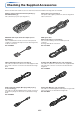
Checking the Supplied Accessories Remove the main unit and the accessories from the box and check that the following items are included. Power cable (1.8 m / 5.9 feet) [1] This power cable supplies power to the unit. See Page E-22 about connections.
Checking the Supplied Accessories USB cable (type A, 2 m / 6.6 feet) [1] Used to perform mouse operations on a computer using the projector’s remote control unit. Connections are described on Page E-32. No. 781807800 Wireless LAN card [1] Storage case (for projector and accessories) [1] This is a case designed for storing the projector and its accessories. Use this carrying case when storing or moving the projector.
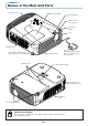
Names of the Main Unit Parts Terminal cover Lamp cover [E-62] Zoom ring [E-25] ESS N PRO OPE T ME SO Remote control sensor [E-12] UR NU CE ICK U QUMEN US AT ST AU AN ST DB TO Y P TO RE OP SS EN Focus ring [E-26] Lens US B Ventilation slots Front adjuster button [E-26] (There is also one on the right side.) Lens cap Remove before use. Attach the lens cap after use to protect the lens. Exhaust vents Ventilation slots Rear adjuster [E-26] Built-in security slot (See description below.
Names of the Main Unit Parts STANDBY button [E-22] STATUS indicator [E-22, 58] STANDBY indicator [E-22, 58] STATUS STANDBY Buttons used in menu and quick menu operations [E-36, 37] SELECT (왖왔왗왘) buttons SOURCE button [E-27] AUTO button [E-27] SOURCE AUTO MENU QUICK MENU ENTER button [E-23] MENU button [E-37] QUICK MENU button [E-36] Speaker Remote control sensor [E-12] Used when using a CompactFlash card or a wireless LAN card.
Names of the Remote Control Parts Names of Parts the Remote Control Unit Included with the U7-132SF, U7-132hSF and U7-137SF Infrared transmitter [E-12] Laser transmitter [E-31] STANDBY button [E-22, 24] This button is used to switch ON the power aand set the unit to the STANDBY mode.
Preparing the Remote Control Inserting the Batteries When using the remote control for the first time, install the batteries that were supplied. the battery compartment Insert the batteries to match (A) Leaving a little space in the front, close 1 Slide cover (located on the bottom 2 the “+” and “–” as indicated in- 3 the lid, (B) then with the back pressed tightly, of the remote control) and pull off. side the compartment. (C) press the lid towards the front.
The Procedure Up to Projecting to the Screen Perform setup adjustments in the following order. 1 Position the projector Determine the locations to set up the screen and the projector. See “Placement Guide” on Page E-14. 2 Connect the video equipment and personal computer Connect your equipment to the projector. When making connections with the personal computer’s DVI connector or RGB connector, see “Connections with Personal Computers” on Page E-15.
Placement Guide • Use this information as a guide to find out about the screen size when the projector is placed at a certain location, or to find out the approximate size of a screen that will be required. • The projection distance over which focussing is adjustable is 1.20 m (3.9 feet) to 11.02 m (36.15 feet). The projector should be placed within this range. • When suspending the projector from the ceiling, change the projection method. See “Vertical Flip / Horizontal Flip” on E-50.
Connecting Personal Computers and Video Equipment Connecting this unit with a personal computer permits presentation data to be projected as a large screen display at conferences, lectures, and on other occasions. Furthermore, connecting this unit to a DVD player or other video equipment source in combination with an audio/video amplifier and speaker system will allow you to enjoy convincing home theater.
Connecting Personal Computers and Video Equipment Personal Computers with a Mini D-Sub 15-Pin Connector • • When connections are made to the RGB connector of this projector, make these connections using the supplied RGB signal cable. Please orient the connector to mate properly when before inserting it, then turn the screw knobs to secure the connector to that of the projector.
Connecting Personal Computers and Video Equipment To Output the External Output Signal of a Notebook Computer When projection will be with a notebook computer connected, knowledge will be required for the cable connection and notebook computer startup procedure as well as the operation that follows notebook startup. Please consult the instruction manual of your notebook computer or the on-line help while performing the following procedure.
Connecting Personal Computers and Video Equipment Connections with Composite Signals Video Equipment with VIDEO Connectors • Make the connection to the VIDEO connector of the projector using the supplied Video cable. • The input setting of the VIDEO connector has been set to “Auto” at the factory; however, if the projector does not project, please change the input setting to “Your Country’s Television Broadcast System” using the menu sequence of [Setup] → [Input Format] → [Video].
Connecting Personal Computers and Video Equipment Connections with Component Signals When the Video Equipment Has a YCbCr Connector or YPbPr Connector • When connecting the computer to the projector’s RGB connector, connect using a separately sold component cable. • The projector has been set to “Auto” at the factory; however, if it does not project, please change the input setting to “Component” using the menu sequence of [Setup] → [Input Format] → [RGB]. See “Input Format” on Page E-52.
Connecting Personal Computers and Video Equipment Connections with Audio Connectors * Make the connection to the projector’s AUDIO connector using the supplied audio cable. When the audio jack of the equipment that is to be connected is of the RCA phono type, make connection via the supplied audio conversion adapter. * The built-in speaker of the projector provides monaural audio. To enjoy convincing audio reproduction, please connect the audio output of the video equipment to your audio system.
Connecting Personal Computers and Video Equipment Connections with the RGB OUT Connector • • • • The image from the computer connected to the DVI or RGB IN connector is output. The image of the connector selected with the input selection function is output. If an input other than DVI or RGB is selected with the input selection function, the output does not switch. While controlling the personal computer in front of you, the same screen can be projected with the projector.
Power Cable Connections and Switching the Power On/Off There is an order in which the power cable is connected and the power is switched on/off. Operating 1 Connect the AC IN connector of the projector and the power outlet using the supplied power cable. The STANDBY indicator will light in amber, and the unit will enter the standby mode. Lit amber STATUS To wall outlet STANDBY D VI Firmly plug in all the way. 2 Switch on the projector power Press the STANDBY button.
Power Cable Connections and Switching the Power On/Off When [Menu Language Select] is Displayed Upon Switching On the Power The first time the power is switched on after purchase, [Menu Language Select] will be displayed. Follow the procedure described below and select the display language of the projector. If the image is blurred, turn the focus ring counterclockwise or clockwise to focus it. See Page E-26. Cursor 1 Press the SELECT (왖왔) buttons and align the deep blue cursor with [English].
Power Cable Connections and Switching the Power On/Off Finishing 1 Switch off the power of the connected equipment 2 Switch off the power of the projector Press the STANDBY button. STANDBY RGB STATUS LASER VIDEO MENU STANDBY AUTO QUICK Q (button on main unit) The [Power Off] display appears. When the level gauge reaches maximum, the projection screen will go off (in about 5 seconds) and the projector will enter the power-off operation.
Adjustment of the Projection Screen Switch on the power of the connected equipment and make the adjustments with the video signal being input to the projector. Adjustment of the Projection Screen 1 Turn the zoom ring to adjust the screen size of the projection image. Adjust the image to match the desired screen size. When outside of the adjustment range, move the projector to the rear or forward. Zoom ring 2 Adjust the projection image to the screen. Check that the screen is set level and vertically.
Adjustment of the Projection Screen 3 Turn the focus ring and adjust the focus of the screen Focus ring Making Adjustments with the Adjusters Raising the projection image While viewing the projection image, (1) press and hold the front adjuster buttons located at the left and right and, (2) raise the projector to align the image with the screen, then release your fingers. Turn the left and right front adjusters for fine adjustment. Adjust so that there is no shaking of the projector.
General Operation This section describes the use of direct operation with the main unit or remote control buttons. For information about operation using the menu, see “Menu Operation Method” on Page E-27 and the various items on Pages E-44 to E-57. Input Selection Select the input signal to be projected. Press the SOURCE button on the projector or the RGB or VIDEO button on the remote control unit. When one of the buttons is pressed, a menu for selecting the source appears.
General Operation Freezing a Moving Picture This function is used to stop and view a moving picture. Note that the input image continues to advance even though the picture there is a still picture condition. STANDBY A press of the FREEZE button changes the screen to a still picture. A further press returns the screen to a moving picture.
General Operation Enlargement of the Image and Video Movement This function digitally enlarges the personal computer image and video image. (1) Press the ZOOM button to enlarge the image. The zoom display appears when the ZOOM button is pressed. STANDBY LASER VIDEO RGB AUTO MENU QUICK Q When the 왖 button is pressed, the image is enlarged approximately 2 times, and when the 왔 button is pressed the image is reduced (returning to 1:1).
General Operation Using the Presentation Timer The presentation is given while checking the timer displayed on the screen. The gauge display allows the remaining time to be known at a glance. (1) Press the TIMER button to show the settings display. The display will close when an operation has not been made for about 10 seconds.
General Operation Using the Laser Pointer The remote control unit’s laser pointer can be used to point to the section currently being explained, making presentations more effective. CAUTION Do not look at the laser pointer’s light source. Be sure to heed the following. Pointing the laser beam at the eyes could lead to reduced vision or vision impairment. • Never look at the laser pointer’s light source. • Do not point the laser beam at people. • Do not let children use the laser pointer.
General Operation Performing Mouse Operations on the Computer with the Remote Control Unit When a computer and the projector are connected, mouse operations can be performed on the computer using the projector’s remote control unit. When projecting images from the computer, the projector can be operated and mouse operations on the computer performed with the same remote control unit, making for efficient presentations.
General Operation Controlling the Projector from a Computer Use the control connector if the projector cannot be operated with the remote control unit, for example when it is suspended from the ceiling. RS-232C connections Use the order-made cable (D-Sub 9-pin/DIN 9-pin) to connect the computer’s RS232C connector to the projector’s “PC CONTROL” connector.
General Operation Protecting the Projector with the Security Lock A password can be registered and the security lock set in order to protect the projector from unauthorized use. Registering the password The password is registered using the menus. For instructions on operating the menus, see “Menu Operation Method” on E-37. (1) Select “Security Lock” in the “Option” menu and set it to “Enable”. The menu closes and the password registration display appears.
General Operation If the password input display appears when the power is turned on When a password has been registered, the “Password” input window appears on the projected image when the power is turned on. The projector continues projecting this image until the correct password is input. At this time, only the STANDBY button (power off) works. Use the procedure described below to input the registered password. For instructions on registering the password, see E-34.
General Operation Using the Quick Menu (1) This function permits frequently used adjustments to be performed quickly. Note that the Quick Menu will not be displayed unless the signal of the connected equipment is input. Please select the input that you wish to adjust. Main unit operation (1) Press the QUICK MENU button to display the quick adjustment display. Further presses cause the adjustment display to change in sequence. Press the SELECT 왖 or 왔 button to switch to the desired adjustment display.
Menu Operation Method • This section describes only the menu operation method. Please see this item should you need information while performing menu operations. • For information about a menu function, adjustment, or setting, please see one of the pages containing such descriptions. • Adjustments and settings are made by projecting an image and adjusting to an optimum condition. • The remote control should be pointed toward the remote control sensor of the projector and operated.
Menu Operation Method Menu Screen Names and Functions Menu Name This is the title of the menu. There is a change to the title screen when the menu is selected. The cursor moves to the selected menu name. Cursor (Deep Blue) This permits setting/adjustment of the item located at the cursor position. Item Name This is the name of the adjustment or setting. Icon: Pressing the ENTER button displays the sub menu or setting contents.
Menu Operation Method Performing Menu Operations • Only “Setup”, “Options” and “Info.” can be selected when no signal is being input. • The menu display will close if, after pressing a button, the next button operation is not made within 30 seconds. • The adjustment and the setting values are stored even when the power is switched off or the plug is disconnected from the power outlet. (Note that some items are not stored.
Menu Operation Method Displaying the Cursor 3 Press the 왔 SELECT button to display the item name selection cursor. STANDBY LASER VIDEO RGB AUTO MENU QUICK Q R-CLICK/ CANCEL ENTER FREEZE This condition allows selection of the item name.
Menu Operation Method Closing the Menu 6 Press the MENU button and close the menu display STANDBY RGB LASER VIDEO AUTO QUICK MENU Q R-CLICK/ CANCEL ENTER FREEZE MUTE TIMER Selecting Another Menu Name with Remote Control Operation When a sub menu is displayed, press the CANCEL button and close the sub menu. Press the CANCEL button again to turn off the item name cursor.
Menu Operation Method List of Item Names Offering Input Selection and Adjustments/Settings The item names that can be adjusted/set will differ depending on the input signal.
Menu Operation Method DVI t nt R lo g om ta l A pon na e og gi al m co an I DV di na l en n po ig tS pu Sub Menu Item Name RGB E GB S- O VI D Im EO ag N eV et w iew or e k r Imput Terminal 嘷 嘷 嘷 嘷 嘷 嘷 嘷 嘷 E-51 嘷 嘷 嘷 嘷 嘷 嘷 嘷 嘷 嘷 E-51 Menu Position 嘷 嘷 嘷 嘷 嘷 嘷 嘷 嘷 嘷 E-51 Lamp Mode 嘷 嘷 嘷 嘷 嘷 嘷 嘷 嘷 嘷 E-52 DVI 嘷 嘷 嘷 嘷 嘷 嘷 嘷 嘷 嘷 E-52 RGB 嘷 嘷 嘷 嘷 嘷 嘷 嘷 嘷 嘷 E-52 Video 嘷 嘷 嘷 嘷 嘷 嘷 嘷 嘷 嘷 E-52 S-Video 嘷 嘷 嘷 嘷 嘷 嘷 嘷
Image • Perform this operation while projecting the picture for which the adjustment/setting will be made. • Select the menu name “Image”. See “Menu Operation Method” on Page E-37 for information about performing menu operations. The item name display will differ depending on the input signal. See “List of Item Names Offering Input Selection and Adjustments/Settings” on Page E-42.
Image Fine Picture Adjust this when the picture shows a lack of color fidelity or flickering. Select the “Fine Picture” item name and adjust with the SELECT (왗왘) buttons so that the lack of color fidelity or the flickering disappears. H Position Adjust this when the picture is shifted to the left or right. Select the “H Position” item name and adjust with the SELECT (왗왘) buttons. V Position Adjust this when the picture is shifted up or down.
Color • Do the following operation while displaying the image you want to adjust or set. • Select the menu name “Color”. See “Menu Operation Method” on Page E-37 for information about performing menu operations. The item name display will differ depending on the input signal. See “List of Item Names Offering Input Selection and Adjustments/Settings” on Page E-42. Quick Color Adj. Select the preset color mode. Select the “Quick Color Adj.
Color Color Temp. The screen color is affected by the color of the illumination and other extraneous light. This function adjusts the white, which is the reference color for video equipment, and improves the quality of color reproduction. Adjustment can also be used to enhance skin colors. Select the item name “Color Temp.” and select the setting contents with the SELECT (왗왘) buttons. Low ............ Medium ...... Normal ....... High ............
Color White Balance The black and white levels of the analog RGB or DVI analog input signals being projected are adjusted automatically for the computer. This increases color reproducibility. 1 Select the item name [White Balance] and press the ENTER button. 2 The screen background color of the connected personal computer will be set to black. The display will change to [Input Black Signal]. 3. Press the ENTER button. The display will change to [Adjusting Black] and the black level will be adjusted.
View • Perform this operation while projecting the picture for which the adjustment/setting will be made. • Select the menu name “View”. See “Menu Operation Method” on Page E-37 for information about performing menu operations. The item name display will differ depending on the input signal. See “List of Item Names Offering Input Selection and Adjustments/Settings” on Page E-42. Aspect This function sets the horizontal and vertical picture proportions of the input signal.
View Vertical Flip / Horizontal Flip This is the selection of how images are projected on the screen. Set this when the projector is suspended from the ceiling, installed on its back, etc. Select the item name “Vertical Flip” or “Horizontal Flip” and select the setting contents with the SELECT (왗왘) buttons.
Setup • Select menu name “Setup”. See “Menu Operation Method” on Page E-37 for information about performing menu operations. The item name display will differ depending on the input signal. See “List of Item Names Offering Input Selection and Adjustments/Settings” on Page E-42. Auto Source The Auto Source function automatically detects the input signal when the power supply is switched on and when the input is switched.
Setup Lamp Mode Use this if the picture is projected on a small screen and the picture is too bright or when projecting images in dark rooms. Select the item name “Lamp Mode” and select the setting contents with the SELECT (왗왘) buttons. Eco ............. The lamp brightness is set to 80% and the lamp life is extended. (STATUS indicator is green) Normal ....... The lamp brightness is set to 100% and the screen is bright. (STATUS indicator is off) Note: Frequent switching this mode can degrade the lamp.
Setup Presentation Timer The presentation is given while checking the timer displayed on the screen. The gauge display allows the remaining time to be known at a glance. Select the item name “Presentation Timer” and select the setting contents with the SELECT (왗왘) buttons. Setting contents: Off, 10 min., 20 min., 30 min., 40 min., 50 min., 60 min. To start the timer... Press the MENU button and open the menu. The timer display will appear at the lower right and the timer will start.
Option • Select menu name “Option”. See “Menu Operation Method” on Page E-32 for information about performing menu operations. The item name display will differ depending on the input signal. See “List of Item Names Offering Input Selection and Adjustments/Settings” on Page E-42. Language This function sets the language that is displayed on screen in the messages and menu displays. Select item name “Language” and press the ENTER button to open the Language sub menu.
Option Startup Screen This is the selection of whether or not to display the logo screen at startup time. Select item name “Startup Screen” and select the setting contents with the SELECT (왗왘) buttons. Logo ........... Displays the logo. Blank .......... Does not display the logo. Note: When “Logo” is selected at the startup screen, the “PLUS” logo is displayed. Security Lock A password can be registered and the security lock set in order to prevent unauthorized use of the projector.
Info. • Select menu name “Info.”. See “Menu Operation Method” on Page E-37 for information about performing menu operations. The item name display will differ depending on the input signal. See “List of Item Names Offering Input Selection and Adjustments/Settings” on Page E-42. Status This displays information about the equipment. Select item name “Status” and press the ENTER button. There is a change to the status display. Press the CANCEL button to return to the menu.
Info. Resolution / Frequency This function displays the resolution and frequency of the detected input signal. Lamp Timer This displays the lamp timer. This projector has an Eco mode function. The lamp life will differ between Normal mode and Eco mode. Lamp Life Use only in Normal mode: approx.2000 hours Use only in Eco mode: approx.3000 hours * Lamp life will differ when there has been switching between the modes.
When an Indicator is Lit or Blinking The indicators on the projector’s control panel lit or blink to notify of problems, as described below. An indicator is also used to notify you of the currently set power mode (under normal circumstances). See “Power Cable Connections and Switching the Power On/Off” on page E-22. STANDBY indicator STATUS indicator Indicator status STATUS STANDBY What you should do When the power is on (Lit green) Standby (Lit amber) It is time to replace the lamp.
Troubleshooting Check the following matters before requesting servicing. Problem Power does not turn on No image is produced Reference Page Check • Is the power cord plugged into a power outlet? • Is the lamp cover properly mounted? • Is the projector’s temperature high? To protect the projector, the power cannot be turned on when the projector’s temperature is abnormally high.
Cleaning • Be certain to disconnect the power plug from the power outlet before cleaning. • Do not spray or otherwise expose the projector, lens, or screen to volatile substances such as insecticides. Do not leave rubber or vinyl products in contact with the projector for long periods. Doing so could cause them to undergo qualitative changes or the coatings may peel, etc. Cleaning a Soiled Projector Main Unit • Wipe with a lint-free, soft, dry cloth.
Replacing the Lamp Cartridge • The lamp that is used as a light source in the projector has a limited service life. The rated service life of the lamp is about 2000 hours (when used in normal mode only). This could be shortened depending on conditions of use and other factors. Note that lamp life will be extended when the projector is often used in Eco mode.
Replacing the Lamp Cartridge 1 Unplug the power cord. 2 Remove the lamp cover. (1) Turn the lamp cover’s set screw counterclockwise and loosen until the screw turns freely. (The screw does not come off.) (2) Open the lamp cover a little, then pull it in the direction of the arrow and remove it. 3 Remove the lamp cartridge. (1) Turn the lamp cartridge’s two set screws counterclockwise and loosen them until the screws turn freely. (The screws do not come off.
Replacing the Lamp Cartridge 4 Mount the new lamp cartridge. (1) Place the lamp cartridge with its socket facing to the left and push it in slowly. (Line it up with the screw holes in the projector.) (2) Turn the two lamp cartridge screws clockwise to tighten them. 5 Mount the lamp cover. (1) Set the tip of the lamp cover in place, then close the lamp cover. (2) Turn the lamp cover’s screw clockwise to tighten it. 6 Reset the Lamp Timer. Connect the power cable, switch on the power, and then reset.
Specifications Model U7-132SF/U7-132hSF/U7-137SF Optical Method of projection : DMD Lamp Projection lens : Image size Light Output Contrast Ratio DLP™ (single chip DMD) 0.7 inches 1024⳯768 dots 300 W high pressure mercury lamp Manual zoom (⳯1.2), Manual focus F = 2.6 – 2.8, f = 22.1 – 25.6 mm Minimum 34 inch (at projection distance of 1.20 m / 3.9 feet telephoto) Maximum 300 inch (at projection distance of 9.47 m / 31.
Table of Supported Frequencies The projector automatically identifies the signal input from the computer and selects the optimum resolution as shown on the table below. Manual adjustments may be required for some input signals. See “Picture Adj. / Fine Picture / H Position / V Position” on page E-44, 45.
E-66 Unit: mm (inch) 83 (3.3) 258 (10.2) 320 (12.
2005