
Installation Guide

8" - 12"
8" - 12"
36"
Utility Trim
8" - 12"
Align Slots
in Lineal
and Utility
Trim
Fig.1
Fig. 2
Fig. 3
frieze, rake and band boards
accessories installation
4”
3/4”
8" - 12"
1/4" Above
Drip Cap
Fig. 4
Fig. 5
Fig. 6
36
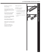
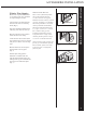
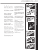
Band Board Installation
Option 1: Choose either a 3.5˝ or
5˝ lineal, depending on the look you
want to achieve.
For easy installation (when possible),
lock the lineal onto the last full
course of siding.
Nail every 8˝ to 12˝ with nail
centered in the nailing slots.
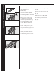
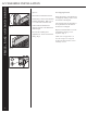
A drip cap must be installed along
with a starter strip or J-Channel to
recieve the 1st course of siding above
the lineal. (Fig. 4, 5 & 6)
The drip cap should be formed so
that it extends up the wall 4˝ and
extends over the face of the lineal by
3/4˝. (Fig. 4)
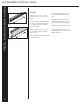
Proceed with standard panel
application by installing the siding
into the lineal J-Channel.
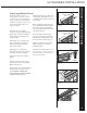
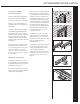
Option 2: (Fig. 2) & ( Fig. 3)
Determine the location of the band
board in relation to the siding making
certain it does not interfere with the
butt of the siding panel.
Strike a chalk line and install utility
trim along the line nailing every 8˝ to
12˝ with nails centered in the nailing
slots.
Lock the band board into the utility
trim and nail every 36˝. (Fig. 2)
Once the band board is in place,
install another piece of utility trim by
aligning the nails slots of the finish
trim with the band board lineal. You
may have to shim the utility trim.
Nail every 8˝ to 12˝.
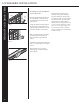
To install siding panels, use a snap-
lock tool to create tabs in each panel
and install them into the utility trim.
(Fig. 3)
Once the siding is in place, install
a drip cap (field or factory formed)
on top of the band board lineal to
prevent water intrusion. (Fig. 4)
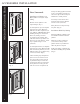
Finally, for horizontal siding
applications,
install a universal starter strip over
the drip cap nailing every 8˝ to 12˝
centered in slots. Make sure to attach
starter strip 1/4˝ above drip cap to
allow siding to lock. (Fig. 5)
For vertical siding applications,
install a J-Channel over the drip cap
and proceed with standard panel
application.
Drill 1/8˝ holes in base of J-Channel
every 24˝ to allow for water to run
off. (Fig. 6)
continued on next page