
Installation Guide


ENGINEERED WOOD CONSTRUCTION GUIDE
■
FORM NO. E30V
■
© 2011 APA – THE ENGINEERED WOOD ASSOCIATION
■
WWW.APAWOOD.ORG
68
Roof Construction
APA Panel Roof Diaphragms
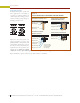
With only slight design modifications, any APA panel roof deck system described in the previous sections will also
function as an engineered diaphragm to resist high wind and seismic loading. A diaphragm’s ability to function effec-
tively as a beam, transferring lateral loads to shear walls, is related to the quality of the connections. Nailing is critical
since shear loads are trans mitted through these fasteners. Common nails provide required strength. Other nail types
may be used when their lateral bearing values are considered in the design. Load-carrying capacity is highest when the
diaphragm is blocked.
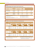
Where Performance Category 1-1/8 roof panels are desired, such as for Heavy Timber construction (see page 75), shear
values for Performance Category 19/32 panels are used. Blocked shear values for Performance Category 1-1/8 panels
may be obtained by specifying stapled tongue-and-groove edges. Staples shall be 16 gauge, 1 inch long with a 3/8-inch
crown, driven through the tongue-and-groove edges 3/8 inch from the joint so as to penetrate the tongue with both legs
of the staple. Staples shall be spaced at one-half of the diaphragm boundary nail spacing for Cases 1 and 2, and at one-
third the diaphragm boundary nail spacing for Case 3 through 6, as illustrated in Table 38.
Table 38 gives panel and fastening recom men dations for roof diaphragms. Panels and framing are assumed already
designed for perpendicular loads. To design a diaphragm, follow these steps:
1. Determine lateral loads and resulting shears.
2. Determine nailing schedule (Table 38). Consider load direction with respect to joints.
3. Compute chord stress due to bending moment.
Provide adequate splices. Check deflection. Check
anchorage of boundary framing (e.g., chords) to walls.
For information about developing higher dia-
phragm shears than shown in Table 38, see APA
Design/Construction Guide: Diaphragms and Shear Walls,
Form L350.
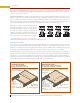
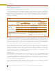
FIGURE 25
OPEN SOFFIT
Shim at each rafter for flush joint, if necessary,
at change of panel thickness
APA RATED
SHEATHING
or any appropriate
APA Exterior or Exposure 1
panel grade and thickness for
desired appearance and
load-carrying capacity
(see Tables 30 and 36)
Strength axis
Protect edges of
Exposure 1
sheathing
against
weather
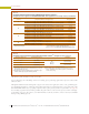
FIGURE 26
CLOSED SOFFIT
Protect edges of
Exposure 1
sheathing
against
weather
Any appropriate
grade of Exterior panels
for soffit (see Table 36)
Continuous
screened vent
or louvered vent
Leave 1/8" space at all panel end and edge joints.
Support all panel edges.
APA RATED SHEATHING
Strength axis