
Installation Guide


ENGINEERED WOOD CONSTRUCTION GUIDE
■
FORM NO. E30V
■
© 2011 APA – THE ENGINEERED WOOD ASSOCIATION
■
WWW.APAWOOD.ORG
69
Roof Construction
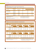
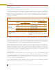
TABLE 38
ALLOWABLE SHEAR (POUNDS PER FOOT) FOR HORIZONTAL APA PANEL DIAPHRAGMS WITH
FRAMING OF DOUGLAS-FIR, LARCH OR SOUTHERN PINE
(a)
FOR WIND
(b)(c)
OR SEISMIC LOADING
(c)
Panel Grade
Common
Nail Size
(f)
Minimum
Nail
Penetration
in Framing
(in.)
Minimum
Nominal
Panel
Thickness
(in.)
Minimum
Nominal
Width of
Framing
Members
at
Adjoining
Panel
Edges and
Bound-
aries
(g)
(in.)
Blocked Diaphragms Unblocked Diaphragms
Nail Spacing (in.) at
diaphragm boundaries
(all cases), at continuous
panel edges parallel
to load (Cases 3 & 4),
and at all panel
edges (Cases 5 & 6)
(d)
Nails Spaced 6" max. at
Supported Edges
(d)
Case 1 (No
unblocked
edges or
continuous
joints
parallel
to load)
All other
configurations
(Cases 2, 3,
4, 5 & 6)
6 4 2-1/2
(e)
2
(e)
Nail Spacing (in.) at
other panel edges
(Cases 1, 2, 3 & 4)
(d)
6 6 4 3
APA
STRUCTURAL I
grades
6d
(h)
1-1/4 5/16
2
3
185
210
250
280
375
420
420
475
165
185
125
140
8d 1-3/8 3/8
2
3
270
300
360
400
530
600
600
675
240
265
180
200
10d
(i)
1-1/2 15/32
2
3
320
360
425
480
640
720
730
820
285
320
215
240
APA RATED
SHEATHING
APA RATED
STURD-I-
FLOOR
and other
APA grades
except Species
Group 5
6d
(h)
1-1/4
5/16
2
3
170
190
225
250
335
380
380
430
150
170
110
125
3/8
2
3
185
210
250
280
375
420
420
475
165
185
125
140
8d 1-3/8
3/8
2
3
240
270
320
360
480
540
545
610
215
240
160
180
7/16
2
3
255
285
340
380
505
570
575
645
230
255
170
190
15/32
2
3
270
300
360
400
530
600
600
675
240
265
180
200
10d
(i)
1-1/2
15/32
2
3
290
325
385
430
575
650
655
735
255
290
190
215
19/32
2
3
320
360
425
480
640
720
730
820
285
320
215
240
(a) For framing of other species: (1) Find specific gravity for species
of lumber in the AF&PA National Design Specification (NDS). (2)
Find shear value from table above for nail size for actual grade. (3)
Multiply value by the following adjustment factor: Specific Gravity
Adjustment Factor = [1 – (0.5 – SG)], where SG = specific gravity of
the framing. This adjustment shall not be greater than 1.
(b) For wind load applications, the values in the table above shall be
permitted to be multiplied by 1.4.
(c) For shear loads of normal or permanent load duration as defined
by the AF&PA NDS, the values in the table above shall be multiplied
by 0.63 or 0.56, respectively.
(d) Space nails maximum 12 inches o.c. along intermediate framing
members (6 inches o.c. when supports are spaced 48 inches o.c.
or greater). Fasteners shall be located 3/8" from panel edges.
(e) Framing at adjoining panel edges shall be 3" nominal or wider,
and nails shall be staggered where nails are spaced 2 inches o.c.
or 2-1/2 inches o.c.
(f) See Table 5, page 14, for nail dimensions.
(g) The minimum normal width of framing members not located at
boundaries or adjoining panel edges shall be 2".
(h) 8d is recommended minimum for roofs due to negative pressures
of high winds.
(i) Framing at adjoining panel edges shall be 3" nominal or wider,
and nails shall be staggered where 10d nails having penetration
into framing of more than 1-1/2" are spaced 3 inches o.c.
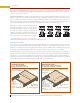
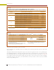
Note: Design for diaphragm stresses depends on direction of con-
tinuous panel joints with reference to load, not on direction of long
dimension or strength axis of sheet. Continuous framing may be in
either direction for blocked diaphragms.
Load
Load
Case 5
Case 6
Continuous panel joints
Diaphragm boundary
Load
Load
Case 2
Case 4
Load
Load
Case 1
Case 3
Blocking typical
if used
Framing typical
Blocking typical
if used
Framing typical
Blocking typical
if used
Framing typical
Continuous panel joints
Diaphragm boundary
Continuous panel joints
Diaphragm boundary