
User Manual


PNI Sensor Corporation DOC# 1014177 r08
Prime User Manual – July 2011 Page 8
4.2.3 Mount in a physically stable location
Choose a location that is isolated from excessive shock, oscillation, and vibration. The
Prime works best when stationary. Any non-gravitational acceleration results in a
distorted reading of Earth’s gravitational vector, which affects the heading measurement.
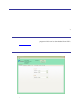
4.2.4 Location-verification testing
Location-verification testing should be performed at an early stage of development to
understand and accommodate the magnetic distortion contributors in a host system. The
data logger in StudioPrime (see Section 5.6) can be used to perform the following tests.
Determine the distance range of field distortion
Place the compass in a fixed position, then move or energize suspect components
while observing the output to determine when they are an influence.
Determine if the maximum field is within the linear range of the compass
With the compass mounted, rotate and tilt the system in as many positions as
possible. While doing so, monitor the magnetic sensor outputs, observing if the
maximum useable range is exceeded.
4.3 Mounting
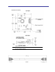
Refer to Figure 3-1 for dimensions, mounting holes, and reference frame orientation.
The Prime is pre-loaded with calibration coefficients so it nominally indicates north per the
arrow on the PCB, assuming a standard orientation (STD 0°) and minimal local magnetic
distortions. It must be aligned within the host system with respect to the mounting holes.
Ensure any stand-offs or screws used to mount the module are non-magnetic.
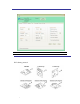
The Prime can be mounted in 24 different orientations, as called out in Table 7-4 and
depicted in Figure 7-2. However, StudioPrime only supports 6 mounting configurations, as
depicted in Figure 5-1. All reference points are based on the white silk-screened arrow on
the top side of the board. The orientation should be programmed in the Prime using the
kSetConfig command and the kMountRef setting, as described in Section 7.3.6.
4.4 Pitch and Roll Convention
As shown in Figure 4-1, roll is defined as the angle rotated around the long axis of the
module while pitch is rotation around shorter axis of the module. Positive pitch is when the
front edge of the board is rotated upward and positive roll is when the right edge of the board
is rotated downward. These two rotations are independent of each other.