
Manual


PNI Sensor Corporation Doc 1017252 r03
RM3100 & RM2100 Sensor Suite User Manual Page 29 of 45
5.2 Initiate Continuous Measurement Mode (0x01)
The MagI2C can either take measurements automatically on a regular frequency (Continuous
Measurement Mode) or by polling for single measurement. This section discusses
Continuous Measurement Mode. See Section 5.3 for polling a single measurement.
To initiate Continuous Measurement Mode, write to the CMM register address, 0x01,
followed by the CMM register contents. To set the rate of data acquisition in Continuous
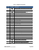
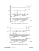
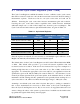
Measurement Mode, see Section 5.2.1. Below are the contents of the CMM register.
Bit #
7
6
5
4
3
2
1
0
Value
LDM
CMZ
CMY
CMX
DRDM1
DRDM0
ALARM
START
Where:
START – A “1” in this bit position initiates Continuous Measurement Mode. To turn
off Continuous Measurement Mode it is necessary to write a “0” to this bit position.
Note that writing to POLL (i.e. initiating a single measurement command) while
operating in Continuous Measurement Mode results in the single measurement
command being ignored.
ALARM – A feature of the MagI2C while operating in Continuous Measurement
Mode is the ALARM bit will go HIGH if a measurement reading is outside a
predefined range of values, set by the Alarm Upper and Lower Limit Registers. This
bit is set to ‘1’ if a limit is exceeded. The ALARM bit is reset by writing a ‘0’ to this
bit. See Section 5.2.2 for additional information.
DRDM – These two bits establish the required condition to trigger the DRDY pin to
HIGH. There are 4 possible conditions, as set out in Table 5-3.