User Manual TCM High-Performance Tilt-Compensated Compass Module
Table of Contents 1 COPYRIGHT & WARRANTY INFORMATION ................................................. 1 2 INTRODUCTION ......................................................................................... 2 3 SPECIFICATIONS ......................................................................................... 3 3.1 Characteristics & Requirements ........................................................... 3 3.2 Mechanical Drawings ......................................................................
6.3.10 Default........................................................................................ 27 6.3.11 Retrieve ...................................................................................... 27 6.4 Calibration Tab .................................................................................... 28 6.4.1 Samples ...................................................................................... 28 6.4.2 Calibration Results ..............................................................
7.3.24 kSetAcqParams (frame ID 24d)................................................... 55 7.3.25 kGetAcqParams (frame ID 25d) .................................................. 56 7.3.26 kSetAcqParamsDone (frame ID 26d) .......................................... 56 7.3.27 kGetAcqParamsResp (frame ID 27d) .......................................... 56 7.3.28 kPowerDownDone (frame ID 28d) ............................................. 56 7.3.29 kFactoryMagCoeff (frame ID 29 d) ..................................
List of Tables Table 3-1: Table 3-2: Table 3-3: Table 3-4: Table 3-5: Table 3-6: Table 4-1: Table 5-1: Table 5-2: Table 5-3: Table 5-4: Table 5-5: Table 6-1: Table 7-1: Table 7-2: Table 7-3: Table 7-4: Table 7-5: Table 7-6: Performance Characteristics1 Absolute Maximum Ratings Electrical Operating Requirements I/O Characteristics Environmental Requirements Mechanical Characteristics TCM Pin Descriptions Magnetic Calibration Mode Summary 12 Point Full-Range Calibration Pattern 12 Point 2D Calibration Patter
1 Copyright & Warranty Information © Copyright PNI Sensor Corporation 2009 All Rights Reserved. Reproduction, adaptation, or translation without prior written permission is prohibited, except as allowed under copyright laws. Revised July 2013. For most recent version visit our website at www.pnicorp.com PNI Sensor Corporation 2331 Circadian Way Santa Rosa, CA 95407, USA Tel: (707) 566-2260 Fax: (707) 566-2261 Warranty and Limitation of Liability.
2 Introduction Thank you for purchasing PNI Sensor Corporation’s TCM XB (pn 12810) or TCM MB (pn 13095) tilt-compensated 3-axis digital compass. The TCM is a high-performance, low-power consumption, tilt-compensated electronic compass module that incorporates PNI’s advanced magnetic distortion compensation and calibration scoring algorithms to provide industry-leading heading accuracy.
3 Specifications 3.1 Characteristics & Requirements Table 3-1: Performance Characteristics1 Parameter Value Accuracy Heading <0.3° rms ≤80° of pitch after Full-Range Calibration <0.5° rms ≤5° of pitch after 2D calibration <2.0° rms ≤2 times the calibration tilt angle when using limited-tilt calibration2 <2.0° rms Resolution 0.1° Repeatability 0.05° rms Range Attitude ≤65° of pitch after Full-Range Calibration Accuracy Pitch ± 90° Roll ± 180° Pitch 0.2° rms Roll ≤65° of pitch 0.
Table 3-2: Absolute Maximum Ratings Parameter Supply Voltage Storage Temperature Minimum Maximum Units -0.3 -40 +10 +85 VDC °C CAUTION: Stresses beyond those listed above may cause permanent damage to the device. These are stress ratings only. Operation of the device at these or other conditions beyond those indicated in the operational sections of the specifications is not implied.
Table 3-4: I/O Characteristics Parameter Value TCM XB Communication Interface TCM MB Communication Protocol Communication Rate Maximum Sample Rate1 Initial power up Time to Initial Good Data2 Sleep Mode recovery RS232 UART CMOS/TTL UART PNI Binary 300 to 115200 baud ~30 samples/sec <210 ms <80 ms Footnotes: 1. The maximum sample rate is dependent on the strength of the magnetic field, and typically will be from 25 to 32 samples/sec. 2. FIR taps set to “0”.
3.2 Mechanical Drawings The default orientation is for the silk-screened arrow to point in the “forward” direction.
The default orientation is for the silk-screened arrow to point in the “forward” direction.
4 Set-Up This section describes how to configure the TCM in your host system. To install the TCM into your system, follow these steps: Make electrical connections to the TCM. Evaluate the TCM using TCM Studio or a binary terminal emulation program, such as RealTerm or Tera Term, to ensure the compass generally works correctly. Choose a mounting location. Mechanically mount the TCM in the host system. Perform a user calibration. 4.
4.2 Installation Location The TCM’s wide dynamic range and sophisticated calibration algorithms allow it to operate in many environments. For optimal performance however, you should mount the TCM with the following considerations in mind: 4.2.1 Operate within the TCM’s dynamic range The TCM can be user calibrated to correct for static magnetic fields created by the host system. However, each axis of the TCM has a calibrated dynamic range of ±125 µT.
Determine if the magnetic field is within the dynamic range of the compass. With the compass mounted, rotate and tilt the system in as many positions as possible. While doing so, monitor the magnetometer outputs, observing if the maximum linear range is exceeded. 4.3 Mechanical Mounting The TCM is factory calibrated with respect to its mounting holes. It must be aligned within the host system with respect to these mounting holes. Ensure any stand-offs or screws used to mount the module are non-magnetic.
4.3.2 Mounting Orientation The TCM can be mounted in various orientations, as shown for the TCM XB in Figure 4-2. All reference points are based on the white silk-screened arrow on the top side of the board. The orientation should be programmed in the TCM using TCM Studio or the kSetConfig command. The default orientation is “STD 0°”. Note: TCM XB is shown. The Z axis sensor and the connector are on the module’s top surface, regardless of model.
5 User Calibration The magnetic sensors in the TCM are calibrated at PNI’s factory in a magnetically controlled environment. However sources of magnetic distortion positioned near the TCM in the user’s system will distort Earth’s magnetic field and should be compensated for in the host system with a user calibration. Examples of such sources include ferrous metals and alloys (ex. iron, nickel, steel, etc.), batteries, audio speakers, current-carrying wires, and electric motors.
5.1 Magnetic Calibration Two fundamental types of magnetic distortion exist, hard-iron distortion and soft-iron distortion. A given component can exhibit both hard-iron and soft-iron distortions. These distortions are reviewed in the ensuing paragraphs, and are followed by discussions on temperature effects and other considerations. For more information on magnetic distortion and calibration, see PNI’s white paper “Local Magnetic Distortion Effects on 3-Axis Compassing” at PNI’s website (http://www.
Other Considerations The TCM measures the total magnetic field within its vicinity, which is a combination of Earth’s magnetic field and local magnetic sources and distortions. While the TCM’s calibration algorithms can compensate for local static magnetic sources, it is not possible to compensate for dynamic changes in the magnetic field. Consequently, it is recommended to keep the TCM away from dynamic magnetic fields.
Before proceeding with a calibration, ensure the TCM is properly installed in the host system, as discussed in Section 4. Also, the software should be properly configured with respect to the mounting orientation, Endianness, north reference, etc. Section 6.4 outlines how to perform a calibration using Studio, while Section 7.3.10 provides a step-by-step example of how to perform a calibration using the PNI protocol. 5.1.
Table 5-2: 12 Point Full-Range Calibration Pattern Sample # Yaw1 Pitch Roll 0° 90° 180° 270° ±5° ±5° ±5° ±5° 30° to 40° -30° to -40° 30° to 40° -30° to -40° 30° 120° 210° 300° > +45° > +45° > +45° > +45° 30° to 40° -30° to -40° 30° to 40° -30° to -40° 60° 150° 240° 330° < -45° < -45° < -45° < -45° 30° to 40° -30° to -40° 30° to 40° -30° to -40° First Circle 1 2 3 4 Second Circle 5 6 7 8 Third Circle 9 10 11 12 Footnote: 1.
Table 5-3: 12 Point 2D Calibration Pattern Sample # Yaw Pitch1 Roll1 1 2 3 4 5 6 7 8 9 10 11 12 0° 30° 60° 90° 120° 150° 180° 210° 240° 270° 300° 330° 0° max. negative 0° max. positive 0° max. negative 0° max. positive 0° max. negative 0° max. positive 0° max. negative 0° max. positive 0° max. negative 0° max. positive 0° max. negative 0° max. positive Footnote: 1. For best results, the tilt experienced during calibration should match that experienced in service.
Note that a similar and acceptable alternative pattern would be to follow the recommended 12 point Full-Range Calibration pattern, but substituting the >±45° of pitch with whatever pitch can be achieved and the ±10° to ±20° or roll with whatever roll can be achieved up to these limits. 5.1.4 Hard-Iron-Only Calibration It is not uncommon for the hard-iron magnetic distortions around the TCM to change.
vector, which in turn will result in an inaccurate heading reading. For this reason, the TCM should be stationary when taking a measurement. As previously mentioned, PNI calibrates the accelerometer in its factory prior to shipment. But over time the bias and offset of the accelerometer will drift. For this reason PNI recommends the accelerometer be recalibrated every 6 to 12 months. The user may return the TCM to PNI for accelerometer calibration, or the user may perform a user accelerometer calibration.
Note: While the TCM is shown removed from the host system, the Accelerometer Calibration may be performed with the TCM mounted in the host system. Figure 5-2: Accelerometer Calibration Starting Orientations 5.2.2 Mag-and-Accel Calibration The TCM allows for a simultaneous magnetometer and accelerometer calibration. This requires a full-coverage calibration pattern, physically stable measurements, and installation in the user’s system so the host system’s magnetic signature is present.
6 Operation with TCM Studio TCM Studio puts an easy-to-use, graphical-user interface (GUI) onto the binary command language used by the TCM. TCM Studio is intended for evaluating, demonstrating, and calibrating the TCM module. The program includes the ability to log and save the outputs from the TCM to a file for off-line evaluation. Check the PNI website for the latest TCM Studio updates at www.pnicorp.com. Note: TCM Studio v3.
6.2 6.2.1 Connection Tab Initial Connection If using the PNI dual-connectorized cable, ensure the batteries are well-charged. Select the serial port the module is plugged into, which is generally COM 1. Select 38400 as the baud rate. Click the button if the connection is not automatic. Once a connection is made the “Connected” light will turn green and the module’s firmware version, serial number, and PCA version will be displayed in the header section. 6.2.
6.2.3 Changing Modules Once a connection has been made, TCM Studio will recall the last settings. If a different module is used, click the button once the new module is attached. This will reestablish a connection, assuming the module baud rate is unchanged. 6.3 Configuration Tab Note: No settings will be changed in the module until the button has been selected. 6.3.1 Mounting Options TCM Studio supports 16 mounting orientations, as illustrated previously in Figure 4-2.
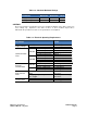
Table 6-1: Mounting Orientations TCM Studio Description Figure 4-2 Description TCM Studio Description Figure 4-2 Description Standard Standard 90 Degrees Standard 180 Degrees Standard 270 Degrees X Sensor Up X Sensor Up Plus 90 Degrees X Sensor Up Plus 180 Degrees X Sensor Up Plus 270 Degrees STD 0° Y Sensor Up Y Sensor Up Plus 90 Degrees Y Sensor Up Plus 180 Degrees Y Sensor Up Plus 270 Degrees Z Sensor Down Z Sensor Down Plus 90 Degrees Z Sensor Down Plus 180 Degrees Z Sensor Up Plus 270 Degrees “
6.3.4 Output The TCM module can output heading, pitch, and roll in either degrees or mils. Click either the or button. The default is . (There are 6400 mils in a circle, such that 1 degree = 17.7778 mils and 1 mil = 0.05625 degree.) 6.3.5 Enable 3D Model TCM Studio’s Test tab includes a live-action 3-D rendering of a helicopter. Some computer systems may not have the graphics capability to render the 3D Model, for this reason it may be necessary to turn off this feature. 6.3.
Acquire Delay The Acquire Delay sets the time between samples taken by the module, in seconds. This is an internal setting that is NOT tied to the time with which the module transmits data to TCM Studio or the host system. Generally speaking, the Acquire Delay is either set to 0, in which case the TCM is constantly sampling or set to equal either the Poll Delay or Sample Delay values.
the button will indicate to the module to take a sample once the minimum change and stability requirements are met. Calibration Points Select the number of points to take during a calibration. The minimum recommended number of points for an initial magnetic calibration is 12, although a Hard-Iron-Only (re)Calibration can be performed with only 6 recommended samples.
6.4 Calibration Tab Note: The default settings are recommended for the highest accuracy and quality of calibration. 6.4.1 Samples Before proceeding, refer to Section 5 for the recommended calibration procedure corresponding to the calibration method selected on the Configuration tab. Clicking the button begins the calibration process. If “Automatic Sampling” is not checked on the Configuration tab, it is necessary to click the button to take a calibration sample point.
6.4.2 Calibration Results Once a calibration is complete, the “Calibration Results” window will indicate the quality of the calibration. This may take a minute or more to populate. The primary purpose of these scores is to confirm the calibration was successful, as indicated by a low Mag and/or Accel CalScore. The other scores provide information that may assist in improving the CalScore, should it be unacceptably high. If either CalScore is too high, click the button to begin a new calibration.
6.4.3 Current Configuration These indicators mimic the pertinent selections made on the Configuration tab. 6.4.4 Options This window indicates how many samples are to be taken and provides real time heading, pitch, and roll information if “HPR During Calibration” is set to , both as defined on the Configuration tab. Audible Feedback If selected TCM Studio will give an audible signal once a calibration point has been taken.
6.5 Test Tab 6.5.1 Current Reading Once the button is selected the module will begin outputting heading, pitch and roll information. Selecting the button or changing tabs will halt the output of the module. Contrast Selecting this box sets the “Current Readings” window to have yellow lettering on a black background, rather than black lettering on a white background. 6.5.
6.5.4 Sync Mode Sync Mode enables the module to stay in Sleep Mode until the user’s system sends a trigger to report data. When so triggered, the TCM will wake up, report data once, then return to Sleep Mode. One application of this is to lower power consumption. Another use of the Sync Mode is to trigger a reading during an interval when local magnetic sources are well understood.
6.6 Log Data Tab TCM Studio can capture measurement data and then export it to a text file. To acquire data and export it, follow the procedure below: Select the parameters you wish to log in the “Data” window. Use Shift -Click and Ctrl-Click to select multiple items. In the screen shot above, “Heading”, “Pitch”, and “Roll” were selected. Click the button to start logging. The button changes to a button after data logging begins. Click the button to stop logging data.
6.7 Graph Tab The graph provides a 2-axis (X,Y) plot of the measured field strength. If “w/o User Cal” graph data is selected, the plot and data provide magnetic field strength measurements after the FIR taps are applied, but prior to applying the user calibration coefficients. If “with User Cal” graph data is selected, the plot and data provide data after applying the FIR filter and the user calibration coefficients.
6.8 System Log Tab The System Log tab shows all communication between TCM Studio and the TCM module since launching TCM Studio. Closing TCM Studio will erase the system log. Select the button, at the bottom right of the screen, to save the system log to a text file.
7 Operation with PNI Binary Protocol The TCM utilizes a binary communication protocol, where the communication parameters should be configured as follows: Table 7-1: UART Configuration 7.
7.2 Parameter Formats Note: Floating-point based parameters conform to ANSIring/IEEE Std 754-1985. Please refer to the Standard for more information. PNI also recommends refer to the user’s compiler instructions to understand how the compiler implements floating-point format. 64-Bit Floating Point (Float64) The 64-bit float format is given below in big Endian. In little Endian, the bytes are in reverse order in 4 byte groups. (eg. big Endian: ABCD EFGH; little Endian: DCBA HGFE).
Signed 16-Bit Integer (SInt16) SInt16-based parameters are signed 16-bit numbers, in 2’s compliment. represents the sign of the value, where 0=positive and 1=negative. 15 8 7 msb 0 7 0 15 8 lsb lsb Bit 15 msb Little Endian Big Endian Signed 8-Bit Integer (SInt8) UInt8-based parameters are unsigned 8-bit numbers. Bit 7 represents the sign of the value, where 0=positive and 1=negative. 7 0 byte Unsigned 32-Bit Integer (UInt32) UInt32-based parameters are unsigned 32-bit numbers.
Unsigned 8-Bit Integer (UInt8) UInt8-based parameters are unsigned 8-bit numbers. 7 0 byte Boolean Boolean is a 1-byte parameter that MUST have the value 0 (FALSE) or 1 (TRUE). 7 0 byte 7.3 Commands & Communication Frames Table 7-2, below, provides the TCM’s command set.
17 kUserCalSampleCount 18 19 20 kCalScore kSetConfigDone kSetFIRFiltersDone 21 kStartContinuousMode 22 kStopContinuousMode 23 kPowerUpDone 24 25 26 27 28 kSetAcqParams kGetAcqParams kSetAcqParamsDone kGetAcqParamsResp kPowerDownDone 29 kFactoryMagCoeff 30 kFactoryMagCoeffDone 31 kTakeUserCalSample 36 kFactoryIAccelCoeff 37 kFactoryAccelCoeffDone 46 kSetSyncMode 47 49 kSetSyncModeResp kSyncRead 7.3.
32 30 38 C7 87” can be decoded to read “TCM5 1208”. Also, the TCM XB is referenced as Type “TCM6” since the number of Type characters is limited to 4. 7.3.3 kSetDataComponents (frame ID 3d) This frame defines what data is output when kGetData is sent. Table 7-3 summarizes the various data components and more detail follows this table. Note that this is not a query for the device's model type and software revision (see kGetModInfo).
Component types are listed below. All are read-only values. kHeading, kPitch, kRoll (Component IDs 5d, 24d, 25d) Provides compass heading, pitch and roll outputs. The heading range is 0.0˚ to +359.9˚, the pitch range is -90.0˚ to +90.0˚, and the roll range is to -180.0˚ to +180.0˚. kTemperature (Component ID 7d) This value is provided by the device’s internal temperature sensor in degrees Celsius, and has an accuracy of ±3° C.
If heading and pitch are set to be output per the kSetDataComponents command, the payload would look like: Example: Payload 2 5 359.9 24 ID Count Heading ID Heading (Float32) Pitch ID 7.3.6 10.5 Pitch Output (Float32) kSetConfig (frame ID 6d) This frame sets internal configurations in the TCM. The first byte of the payload is the configuration ID followed by a format-specific value. These configurations can only be set one at time.
Table 7-4: Configuration Identifiers Settings Config.
kDeclination (Config. ID 1d) This sets the declination angle to determine True North heading. Positive declination is easterly declination and negative is westerly declination. This is not applied unless kTrueNorth is set to TRUE. kTrueNorth (Config. ID 2d) Flag to set compass heading output to true north heading by adding the declination angle to the magnetic north heading. kBigEndian (Config. ID 6d) Sets the Endianness of packets. TRUE is Big Endian. FALSE is Little Endian. kMountingRef (Config.
last sample point. If the user wants to have maximum control over when the calibration sample point are taken then this flag should be set to FALSE. kBaudRate (Config. ID 14d) Baud rate index value. A power-down power-up cycle is required when changing the baud rate. kMilOutput (Config. ID 15d) This flag sets the heading, pitch and roll output to mils. By default, kMilOutput is set to FALSE and the heading, pitch and roll output are in degrees. Note that 360 degrees = 6400 mils, such that 1 degree = 17.
After this second calibration, the coefficients values from the second calibration are immediately applied, even thought kSave has not been sent. If the TCM is now powered down and powered back up again, kMagCoeffSet = 2 would be recalled and its coefficient values would be applied, since kMagCoeffSet = 3 was not saved and kMagCoeffSet = 2 was the last saved calibration set. kAccelCoeffSet (Config.
7.3.9 kSave (frame ID 9d) This frame commands the TCM to save internal configurations and user calibration coefficients to non-volatile memory. Internal configurations and user calibration coefficients are restored on power up. The frame has no payload. This is the ONLY command that causes the device to save information to non-volatile memory. 7.3.10 kStartCal (frame ID 10d) Before proceeding with this section, ensure you are familiar with Section 5.
The CalOption values are given below, along with basic descriptions of the options. Full-Range Calibration - magnetic only (10d = 0Ah) Recommended calibration method when >45° of tilt is possible. 2D Calibration - magnetic only (20d = 14h) Recommended when the available tilt range is limited to ≤5°. Hard-Iron-Only Calibration - magnetic only (30d = 1Eh) Recalibrates the hard iron offset for a prior calibration.
Initiate a calibration using the kStartCal command. Note that this command requires indentifying the type of calibration procedure, for example Full-Range Calibration or 2D Calibration. Follow the appropriate calibration procedure, as discussed in Section 5. If kUserCalAutoSampling was set to FALSE, send kTakeUserCalSample when ready to take a calibration point. If kUserCalAutoSampling was set to TRUE, then look for kUserCalSampCount to confirm when a calibration point has been taken.
would be in the filter. Once the taps are cleared, it is necessary to fully repopulate the filter before data is output. For example, if 32 FIR taps is set, 32 new samples must be taken before a reading will be output. The length of the delay before outputting data is directly correlated to the number of FIR taps. The payload for kSetFIRFilters is given below.
20 05.8693165018301e-2 21 05.2436112653103e-2 22 04.5402682509802e-2 23 03.8014333463472e-2 24 03.0686505921968e-2 25 02.3794805168613e-2 26 01.7646051430536e-2 27 01.2456836057785e-2 28 08.3414139286254e-3 29 05.3097803863757e-3 30 03.2757326624196e-3 31 02.0737124095482e-3 32 01.4823725958818e-3 7.3.13 kGetFIRFilters (frame ID 13d) This frame queries the FIR filter settings for the sensors. Byte 1 should be set to 3 and Byte 2 should be set to 1. Payload 7.3.
7.3.16 kSaveDone (frame ID 16d) This frame is the response to kSave frame. The payload contains a UInt16 error code: 0 indicates no error; 1 indicates an error when attempting to save data to memory. Payload Error Code UInt16 7.3.17 kUserCalSampleCount (frame ID 17d) This frame is sent from the TCM after taking a calibration sample point. The payload contains the sample count with the range of 1 to 32. Payload SampleCount# UInt32 7.3.
DistError: For a magnetic calibration, this score indicates if the distribution of sample points is sufficient, with an emphasis on the heading distribution. The score should be 0. Significant clumping or a lack of sample points in a particular section can result in a poor score. In the event of an aborted calibration the score will be 179.8d, or in the event of an accel-only calibration the score will be 99.99d.
7.3.23 kPowerUpDone (frame ID 23d) This frame confirms the TCM received a command to power up. The TCM will power up when it receives any signal on the native UART Rx line. The frame has no payload. Since the module was previously powered down which drives the RS-232 driver TX line low (break signal), it is recommended to disregard the first byte. 7.3.24 kSetAcqParams (frame ID 24d) This frame sets the sensor acquisition parameters in the TCM.
advantage of running with an AcquireDelay of 0 is the FIR filter can run with a relatively high FIR Tap value to provide stable and timely data. The advantage of using a greater AcquireDelay is power consumption can be reduced, assuming the SampleDelay is no less than the AcquireDelay. SampleDelay The SampleDelay is relevant when the Continuous Acquisition Mode is selected. It is the time delay, in seconds, between completion of the TCM sending one set of data and the start of sending the next data set.
7.3.31 kTakeUserCalSample (frame ID 31d) This frame commands the TCM to take a sample during user calibration. The frame has no payload. 7.3.32 kFactoryAccelCoeff (frame ID 36 d) For the current designated kAccelCoeffSet, this frame clears the accelerometer calibration coefficients and loads the original factory-generated coefficients. The frame has no payload. This frame must be followed by the kSave frame to save the change in non-volatile memory. 7.3.
Example: With a baud rate of 38400, the minimum delay after sending FFh is: Minimum delay at 38400 baud = 7E-4 – (10/38400) = 4.4E-4 seconds = 440 µs Sync Mode generally is intended for applications in which sampling does not occur frequently. For applications where Sync Mode sampling will be at a frequency of 1 Hz or higher, there is a minimum allowable delay between taking samples. This minimum delay between samples (approximately inverse to the maximum sample rate) varies from 100 msec to 1.
7.4 Code Examples The following example files, CommProtocol.h, CommProtocol.cp, TCM.h and TCM.cp would be used together for proper communication with a TCM module. Note: The following files are not included in the sample codes and need to be created by the user: Processes.h & TickGenerator.h. The comments in the code explain what is needed to be sent or received from these functions so the user can write this section for the user’s platform. For example, with the TickGenerator.
k Set Ac qPar ams, k Get Ac qPar ams, k AcqPar ams Done, k Get Ac qPar amsRes p, k Power DoneDown, k Fac t or y Us er Cal , k Fac t or y Us er Cal Done, k Tak eUser Cal Sampl e, k Fac t or y I ncl Cal = 36, k Fac t or y I nc l Cal Done, k Set Sy nc Mode = 46, k Set Sy nc ModeDone, k SyncRead = 49, / / / / / / / / / / / / / / / / / / / / / / / / / / 24 25 26 27 28 29 30 31 36 37 46 47 49 / / Cal Opt i on I Ds k Ful l RangeCal = 10, k 2DCal = 20, k HI Onl yCal = 30, k Li mi t edTi l t Cal = 40, k Acc el C
k Mount k Mount k Mount k Mount k Mount k Mount k Mount k Mount edXUpPl us180 edXUpPl us270 edYUpPl us90 edYUpPl us180 edYUpPl us270 edZDownPl us90 edZDownPl us180 edZDownPl us270 / / Res ul t I Ds k Er r None = 0, k Er r Save, / / / / / / / / / / / / / / / / 9 10 11 12 13 14 15 16 // 0 // 1 }; / / f unct i on t o c al cul at e CRC- 16 UI nt 16 CRC( v oi d * dat a, UI nt 32 l en) { UI nt 8 * dat aPt r = ( UI nt 8 * ) dat a; UI nt 32 i ndex = 0; / / Updat e t he CRC f or t r ans mi t t ed and r ecei v
7.4.2 CommProtocol.h File #pr agma once #i nc l ude " Sy st emSer Por t . h" #i nc l ude " Pr oc es ses. h" // / / CommHandl er i s a base c l ass t hat pr ov i des a cal l back f or / / i ncomi ng mes sages. // c l as s CommHandl er { publ i c : / / Cal l back t o be i mpl ement ed i n der i v ed cl as s.
CommPr ot oc ol ( CommHandl er * handl er = NULL, Ser Por t * s er Por t = NULL) ; v oi d I ni t ( UI nt 32 baud = 38400) ; v oi d SendDat a( UI nt 8 f r ame, voi d * dat aPt r = NULL, UI nt 32 l en = 0) ; v oi d Set Baud( UI nt 32 baud) ; pr ot ec t ed: CommHandl er * mHandl er ; Ser Por t * mSer i al Por t ; UI nt 8 mOut Dat a[ k Buf f er Si z e] , mI nDat a[ kBuf f er Si ze] ; UI nt 16 mEx pect edLen; UI nt 32 mOut Len, mOl dI nLen, mTi me, mSt ep; UI nt 16 CRC( v oi d * dat a, UI nt 32 l en) ; v oi d Co
7.4.3 CommProtocol.cpp File #i nc l ude " CommPr ot oc ol . h" / / i mpor t an obj ec t t hat wi l l pr ovi de a 10mSec t i c k count t hr ough / / a f unct i on cal l ed Ti ck s( ) #i nc l ude " Ti ck Gener at or . h" // Ser Por t i s an obj ec t t hat c ont r ol s t he phy si cal ser i al / / i nt er f ace. I t handl es s endi ng out / / t he c har act er s, and buf f er s t he char act er s r ead i n unt i l / / we ar e r eady f or t hem.
mOut Dat a[ i ndex ++] = c ount >> 8; mOut Dat a[ i ndex ++] = c ount & 0xFF; / / s t or e t he f r ame I D mOut Dat a[ i ndex ++] = f r ameTy pe ; / / c opy t he dat a t o be sent whi l e( l en- - ) mOut Dat a[ i ndex ++] = * dat a++; / / c omput e and add t c r c = CRC( mOut Dat a, mOut Dat a[ i ndex ++] = mOut Dat a[ i ndex ++] = he cr c i ndex ) ; c r c >> 8 ; c r c & 0xFF ; / / Wr i t e bl ock wi l l c opy and send t he dat a out t he s er i al por t mSer i al Por t - >Wr i t eBl ock ( mOut Dat a, i
// // // // s wi t ch( mSt ep) { c ase 1: { wai t f or l engt h by t es t o be r ecei v ed by t he s er i al obj ec t i f ( i nLen >= 2) { Read bl oc k wi l l r et ur n t he number of r eques t ed ( or av ai l abl e) byt es t hat ar e i n t he ser i al obj ec t s i nput buf f er .
/ / go back t o l ook i ng f or t he l engt h by t es . mSt ep = 1 ; } el se { / / Ti c ks i s a t i mer f unct i on. 1 t i ck = 10ms ec . i f ( Ti c ks ( ) > mTi me) { / / Cor r upt ed mes sage. We di d not get t he l engt h we wer e / / expec t i ng wi t hi n 1/ 2sec of r ec ei vi ng t he l engt h byt es .
7.4.4 TCM.h File #pr agma once #i nc l ude " Pr oc es ses. h" #i nc l ude " CommPr ot oc ol . h" // // Thi s f i l e cont ai ns t he obj ect pr ovi di ng communi c at i on t o t he TCM // I t wi l l set up t he modul e and par se pack et s r ecei v ed. // Pr oc es s i s a bas e c l ass t hat pr ov i des TCM wi t h c ooper at i v e // par al l el pr ocess i ng. The Cont r ol met hod wi l l be // cal l ed by a pr oc ess manager on a cont i nuous basi s.
7.4.5 TCM.cpp File #i nc l ude " TCM. h" #i nc l ude " Ti ck Gener at or . h" c ons t UI nt 8 kDat aCount = 4; / / We wi l l be r eques t i ng 4 component s ( headi ng, pi t c h, r ol l , and / / t emper at ur e) // // Thi s obj ec t pol l s t he TCM modul e onc e a second f or // headi ng, pi t ch, r ol l and t emper at ur e.
} / / l oop t hr ough and c ol l ect t he el ement s whi l e( count ) { / / The el ement s ar e r ec ei ved as { t y pe ( i e. k Headi ng) , dat a} s wi t ch( dat a[ pnt r ++] ) / / r ead t he t y pe and go t o t he f i r s t by t e of t he dat a { / / Onl y handl i ng t he 4 el ement s we ar e l ooki ng f or c ase CommPr ot ocol : : k Headi ng: { / / Mov e( sour ce, dest i nat i on, si ze ( by t es ) ) .
def aul t : / / Mes sage i s a f unc t i on t hat di s pl ay s a f or mat t ed s t r i ng / / ( si mi l ar t o pr i nt f ) Mess age( " Unk nown t ype: %02X\ r \ n" , dat a[ pnt r - 1] ) ; / / unk nown dat a t y pe, s o si ze i s unknown, so s ki p ev er yt hi ng r et ur n; br eak; } c ount - - ; / / One l es s el ement t o r ead i n } / / Mes sage i s a f unc t i on t hat di s pl ay s a f or mat t ed s t r i ng / / ( si mi l ar t o pr i nt f ) Mess age( " Headi ng: %f , Pi t ch: %f , Rol l : %f , Temper at
pk t [ 2] = CommPr ot ocol : : kPi t ch; pk t [ 3] = CommPr ot ocol : : kRol l ; pk t [ 4] = CommPr ot ocol : : kTemper at ur e; SendComm( CommPr ot ocol : : kSet Dat aComponent s, pkt , k Dat aCount + 1) ; / / Ti c ks i s a t i mer f unct i on. 1 t i ck = 10ms ec . mTi me = Ti ck s( ) + 100; / / Tak i ng a sampl e i n 1s. mSt ep++; / / go t o nex t st ep of pr ocess br eak; } c ase 2: { / / Ti c ks i s a t i mer f unct i on. 1 t i ck = 10ms ec .