POINT MOBILE CO., LTD. B-9F, 9F, Kabul Great Valley, 32, Digital-Ro 9Gil Geumcheon-gu, gu, Seoul, Korea 153 153-709 www.pointmobile.co.kr Model : Originator : Version : Dept. Date : PM40 Jinny Cho 1.0 PC/PE/ID/PM/QA July. 17 , 2013 th PM40 User Manual The Point Mobile name and logo are trademarks of Point Mobile Co., Ltd. in Korea and many other countries. All rights reserved.
CONTENTS [REFERENCE : The Bookmark is not clearly defined yet] 1. INTRODUCTION ·················································································· 5 Trademarks ································································································ 5 About the PM40 Handy Terminal ································································· 5 Accessories································································································· 5 2.
4.17. 4.18. 4.19. 4.20. 4.21. 4.22. 4.23. 4.24.
9.3. 9.4. 9.5. 9.6. 9.7. 9.8. 9.9. 9.10. 9.11. 9.12. 9.13. 9.14. 9.15. 9.16. 9.17. 9.18.
4
1. Introduction Thank you for purchasing PM40 handy terminal. This manual generally provides you with the safety information and basic features and operations of the PM40 device. Please read all safety precautions and this manual carefully before using your handy terminals and peripherals to ensure safe and proper use. Trademarks The official name of Windows XP is Microsoft Windows XP Operating System. The official name of Windows Vista is Microsoft Windows Vista Operating System.
MicroUSB ActiveSync Cable Others Lanyard Stylus Pen Telescopic/w cord q PM40 handy terminal contains the following items basically: • Handy terminal • MicroUSB ActiveSync Cable • Battery Pack [ STD or ETD ] optional • Stylus Pen with Telescopic/w cord • 5V/1.8A AC Adaptor with MicroUSB type • AC Plugs -KR • LCD Screen Protector Film 1) Material: PET-SKC, Clear, 3H(surface hardness) 2) Size : 44.2mm x 58.6mm x 0.
2.1. General Safety Rules CAUTION · Use only the components supplied by the manufacturer for the specific PM40 being used. · Do not attempt to disassemble the PM40 handy terminal, as it does not contain parts that can be repaired by the user. Any tampering will invalidate the warranty. · When replacing the battery pack or at the end of the operative life of the PM40 handy terminal, disposal must be performed in compliance with the laws in force in your country.
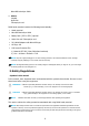
Laser output window LED window Camera window S/N label Laser Light Label Compliance label (Model label) Window mobile label Serial label If the above laser light label is attached to your device, it indicates the product contains a laser engine or laser aimer that emits the laser light. The following information is provided to comply with the rules imposed by international authorities and refers to the correct use of PM40 handy terminal.
2.4. LED Safety The LED output on this device has met IEC62471 LED safety and certified to be under the limits of a CLASS 1 LED product. 2.5. FCC RF Exposure -This device complies with FCC/EU RF exposure guidelines set forth for an uncontrolled environment at the minimum of 15mm distance. -To maintain compliance with RF exposure guidelines for body-worn operation, do not use accessories that contain metallic components. 2.6. CB Scheme This device complies with CB Scheme IEC 60950-1 2.7.
PM40 RF terminals are in conformity with all essential requirements of the R&TTE Directive (1999/5/EC). 0984 This device is marked with in accordance with the Class II product requirements specified in the R&TTE Directive, 1999/5/EC. The device is intended for use throughout the European Community; PAN European Frequency Range: 2.402 ~ 2.480 GHz. Restrictions for use in France are as follows: • Indoor use: maximum power (EIRP*) of 100 mW for the entire 2.400 ~ 2.
3. Getting Started 3.1. Install the Battery The HANDY TERMINAL is shipped with the battery packaged separate from the unit. Follow the steps below to install the battery. 1. Remove the battery compartment door by moving the door’s locks right and lifting up the bottom of door. Battery door lock 2. Insert the battery well with the battery cells facing top. 3. Replace the battery door to start from top to the bottom of door’s lock downwards.
☞NOTE: Two points of Battery guide stopper must be pertinently inserted to rear cover battery guide stopper hole ☞NOTE: The battery door must be installed prior to booting the unit. WARNING: Use only Pointmobile-approved Li-Ion battery packs. Unauthorized battery may result in damage not covered by the warranty. Charge the Batteries 3.2. Handy Terminals ship with only main battery pack significantly charged of power.
Alternatively, it is also possible to recharge the battery pack by using the single slot cradle, the single Ethernet cradle or the 4-slot battery charger. During the charging process the LED positioned at the left upper side of the display is red constant. Once the charging process has been completed this LED is green constant.
WARNING Do not short-circuit the battery pack contacts connecting the positive terminal and negative terminal. This might happen, for example, when you carry a spare battery pack in your pocket or purse; accidental short–circuiting can occur when a metallic object such as a coin, clip, or pen causes direct connection of the contacts of the battery pack (these look like metal strips on the battery pack). Short–circuiting the terminals may damage the battery pack or the connecting object.
3.7. Indicator Icons The command bar, located at the Upper of application screens, provides access to many system functions and programs.
Access the Bluetooth radio Icon Meaning Indicates AC connection mode Indicates WAN (Phone) connection mode Indicates Sound connection mode Indicates LAN / Bluetooth mode Indicates Keypad mode 3.8. Using the Stylus The terminal comes with a stylus included in a loop on the Lanyard. Use this stylus (or your finger) to select or enter information on the touch screen. The stylus functions as a mouse; generally, a tap is the same as a click.
4. Get to Know Your Device 4.1. Feature of Your Device The following list outlines a few of the feature included in your device. 4.2. Ø Ø Ø Ø Ø Ø Ø Ø Ø Ø Ø Ø Ø Ø Ø Ø Ø Ø Ø Ø Ø Ø Ø Ø 4.3. PM40 Handy Terminal Operating Systems: Microsoft Windows Embedded Handheld 6.5 Pro Micro Processor: Cortex-A8 1GHz RAM Memory: 512MB FLASH Memory: 512MB 2.
Receiver Touch screen display Scan key Keyboard (29-key numeric) LED Indicator Shows the information needed to operate your device as follows: Note: The LED is user-programmable. LED Color Meaning Red Lights when main battery is charging. Green Lights when scanned bar code is successfully decoded. Lights when main battery charging has completed. Blue Lights when a scan Pass Red Lights when a scan fails Keypad 29 numeric keypad (includes side scan and volume, power buttons).
4.4. Display Backlight The intensity of the backlight of the touch screen display may be changed, and the backlight may be programmed to turn off after the terminal has been idle for a specified period of time. To adjust the intensity of the backlight while on battery power, tap Start -> Settings -> System > Backlight. Screen Backlight - Battery/External Power Move the slider to adjust the screen backlight while on battery power.
4.6. Using Screen Protectors Pointmobile defines proper use of the terminal touch panel display as using a screen protector and proper stylus. Screen protectors maintain the ongoing integrity (i.e., prevent scratching) of the touch panel, which is why their use is recommended for applications th that at require a high to medium level of interface with the touch panel. Pointmobile also mandates use of the proper stylus, which is one that has a stylus tip radius of no less than 0.8mm.
6. Press gently but firmly. Use the card a necessary to smooth out any air pockets or bumps after allocation 7. 8. Press the Power key to weak the terminal and check the touch panel with the stylus. 9. Verify that the screen accepts input from the stylus as usual. If not, re-apply the screen protector. 10. Press the Power key to put the terminal back in suspend mode. 11. Clean the surface of the screen protector with a clean, non-abrasive, lint-free cloth. 12.
13. For maximum performance, recalibrate the screen Tap Start > Settings > System > Screen 14. Tap Recalibrate the follow the instructions on the screen. 4.8.
LED window Wire spring mount hole Camera window Speaker Battery cover < Wire spring > < Lanyard > Lanyard The HANDY TERMINAL comes with Lanyard and wire spring. You can attach it to the device. Finger Saddle This is a slightly depressed and angled area of the back housing that is designed to cradle or “saddle” your finger while holding the terminal. This unique ergonomic design makes the terminal comfortable to hold and helps prevent you from accidentally dropping the terminal.
etc.). The speaker can also be used for playing sounds (e.g., WAV or MP3 files). The speaker meets the following SPL levels at 10cm: • 500Hz–80dB • 1kHz–90dB • 4kHz–90dB Stylus HANDY TERMINAL is shipped with a stylus inserted in a loop on the Lanyard. Store the stylus in the Lanyard when you’re not using it; see Using the Stylus on paragraph 3.8. 4.9.
4.10. Installing Memory Cards The HANDY TERMINAL supports Micro Secure Digital (SD) memory cards up to 32GB. Sandisk, Kingstone and ATP micro SD recommended To access the Micro SD card slot and insert the card, proceed as follows: 1. Press the Power key to put the terminal in Suspend Mode; see Suspend Mode on paragraph 4.23. 2. Remove the battery door on the back of the unit. 3. Remove the battery and open 4. Open the access door on SD slot in Battery well. 3.
Side Button You can use the Programs Buttons option in the Control Panel to change the functionality of the side buttons. Scan function is assigned by default. EarJack 3.5pi 4pole Jack. This connector supports Ear-Mic headset USB Port This connector supports High speed USB 2.0 communication (up to 480 Mbps) Also external power from the MicroUSB Adaptor that is included with the terminal. When connected to the Handy Terminal MicroUSB Adaptor, the terminal is powered and the main battery pack is charging. 4.
Image engine window (with engine) Image Engine Window The angled image engine reads and decodes most popular bar code symbolizes. For more information, see Using the Image Engine on paragraph 6. 4.13. Bottom Panel Layout I/O connector HandyLink Connector The HandyLink mechanical connector is designed to work exclusively with HANDY TERMINAL peripherals and cables. This connector powers the terminal, charges the main battery, and facilitates communication. This connector supports High speed USB 2.
Pin Description Direction DC IN +5V IN DC IN +5V IN RS-232 Transmitted Data OUT RS-232 Request To Send OUT USB Host +5V OUT USB Host D+ IN/OUT USB Host D- IN/OUT USB Host Detect IN RS-232 Clear To Send IN RS-232 Received Data IN GND GND RS-232 ShutDown IN USB Clinet D+ IN/OUT USB Client D- IN/OUT USB Client +5V IN ☞NOTE: Signals referenced are for a DTE device. 4.14.
4.17. Battery Power The intelligent battery technology inside the terminal features of battery power: • The battery pack The battery works to prevent data loss when the terminal is used over long periods of time. The battery must be charged to full capacity before using the HANDY TERMINAL for the first time! Charge the main battery pack with the Handy Terminal charging cable for a minimum of 5 or 10 hours depending on your battery before initial use. 4.18.
Charging Time The standard capacity 1800mAh Li-ion battery pack requires five hours to charge to full capacity, while the high capacity 3600mAh pack requires eight hours. 4.19. Managing Main Battery Power Data and files saved on the Handy Terminal may be stored in RAM memory; therefore, maintain a continuous power supply to the terminal to help prevent data loss. When you remove a battery pack, insert another charged battery pack in the Handy Terminal.
2. When the reset is complete, the Desktop appears. Hard Reset (Cold Boot) CAUTION: A hard reset erases all of the data and applications stored in RAM memory, reloads the OS, and launches Autoinstall, which installs any CAB or REG files in the \AutoInstall\Cabfile. Hard resets automatically launch a soft reset as part of the boot process if there are CAB files present. 1.
Memory 512MB RAM X 512MB Flash Storage Expansion User accessible Micro SD memory card slot. Display 2.83 in. transmissive active matrix 65K color LCD with backlight, QVGA (240 x 320) Scan 1D engine: N4313 2D engine : N560x Engine Keypad 29-key shifted alpha numeric Audio Built-in microphone and speaker I/O High speed USB 2.0 from cradle (or I/O cable); RS232 (115 Kbps) from cradle Battery Standard Li-ion battery 3.8V / 1800 mAh / 6.8 Wh High capacity Li-ion battery 3.8V / 3600 mAh / 13.
Environmental Independently certified to meet IP65 standards for moisture and particle resistance Dimensions H; 182mm x W; 66.5mm x D; 30.5mm(grip), 39mm(top) Weight 1) 1D ; 2) 2D ; Scanner / Decode Capabilities 2D enginemodel: N560X 2D Imager. Decodes all standard 1D, 2D, Postal, and OCR codes. 1D Laser model: N4313 laser engine. Decodes all standard 1D codes. 293g (318g with High capacity battery) 288g (313g with High capacity battery) 5. Using the Keypad 5.1.
Escape Cancels an action. Enter Performs the same function as the Enter key on a workstation. Power Suspends and resumes the terminal. Scan Activates the image engine to scan a bar code or take an image. Space Moves the cursor one space forward. If you are typing text, it moves the text one space forward as well. 5.4. Alpha/Numeric Modes The keypad defaults to numeric mode. Use the ALPHA key to toggle between numeric and alpha modes.
5.6. BLUE Key Combinations BLUE key modifies the next key pressed to perform specific functions. Key Combination Function BLUE + 1 F1 BLUE + 2 F2 BLUE + 3 F3 BLUE + 4 F4 BLUE + 5 F5 BLUE + 6 F6 BLUE + 7 F7 BLUE + 8 F8 BLUE + 9 F9 BLUE + 0 F10 BLUE + SP Align the screen (Press ESC to exit) BLUE + . Windows Menu BLUE + <- Delete BLUE + Send App 1 BLUE + end App 2 The keypad is color-coded in blue to indicate these key combinations.
☞NOTE: It may not read the barcode due to specular reflection if scanning from directly above. Try again after changing angle. ☞NOTE: It may not read the barcode barcode,, if this handy terminal is too close to or too far from the barcode even if the barcode is within the aiming range. Move the handy terminal toward or away from the barcode slowly and try again. The aiming range is for reference only. ☞NOTE: It may not read the barcode if the barcode surface is curved.
6.3. Depth of Field Depth of Field for N560X ☞NOTE: Test Condition: Room Temperature (Approx. 23°C), 0 Lux. New picture : N5600-IM Rev E.pdf base. 6.4.
1D Symbologies Codabar Code 11 Code 128 Code 39 Code 93 / 93i EAN-8 EAN-13 Interleaved 2 of 5 Reduced Space Symbology UPC-A UPC-E Straight 2 of 5 (IATA) MSI Trioptic Code Code 32 Pharmaceutical (PARAF) Matrix 2 of 5 Telepen GS1-128 ISBT 128 Straight 2 of 5 (Industrial) UPC-A (Coupon Code) UPC-E1 2D Symbologies Aztec Code Data Matrix MaxiCode MicroPDF417 PDF417 QR Code and Micro QR Code Han Xin Composite Codes EAN.UCC Composite Codablock F TCIF Linked Code 39 (TLC39) OCR OCR Postal Codes 6.5.
6.7. Decoding The Handy Terminal supports Full Full-area Imaging decode mode. Full-area Imaging With full-area area imaging the Handy Terminal supports omni omni-directional directional aiming meaning that a positive read can be obtained from many positions. For details, see Omni Omni-Directional Scanning Positions on paragraph 6.10. 6.8. To Decode a Bar Code 1. Tap Start -> Demos -> Scan Demo Demo. 2. Position the Handy Terminal over one of the Sample Bar Codes on paragraph ragraph 6.9.
quickly learn to adapt to different application environments. Image Preview When the imaging process is initiated, the touch screen displays a preview of the object. This is a live video image of what the imager is currently viewing and has a slightly degraded appearance compared to the captured image. This is normal; the captured image has a higher resolution. File Formats The Handy Terminal supports BMP file format only. 7. Using the Laser Engine 7.1.
Code 39 40 mil (*) 26.7in / 67.5cm Code 39 55 mil (*) 31.8in / 80.8cm ☞NOTE: Test Condition: Room Temperature(Approx. 20°C), 450 ~ 500 Lux. ☞NOTE: * = dependent on width of bar code. 7.4. Supported Bar Code Symbologies Symbology Type 1D Symbologies 7.5.
7.9. Scanning Positions The aiming beam must be aimed across the entire bar code to provide you with the best scanning performance. The aiming pattern is smaller when the terminal is held closer to the code and larger when the terminal is held farther from the code. Symbologies with smaller bars or elements (mil size) should be read closer to the unit whereas larger bars or elements (mil size) should be read farther from the unit. 8. Using ScanWedge 8.1.
reception. There is one sound for success and another sound for an error. LED Enables and disables LED notification for decode/data reception. Vibrator Result Type Terminator Enables and disables Vibrator notification for decode/data reception.
other computers. Terminal Serial Number will be in Device Name section by default. You can modify it 9.4. Copyrights Portions of this software are based on NCSA Mosaic. 9.5. Power properties 9.6. Battery tab To see main battery level indicators open Start > Settings > System > Power icon . Set up the USB charging and On / Off 9.7. Advanced tab To adjust power management settings, 1. Select Start > Settings > System > Power > Advanced. 2. Set idle time when on battery power before device suspends.
☞NOTE: 9.8. To save battery life it is recommended to set idle time as short as possible. Alerts Tab Adjust the level of main battery for Low battery message and Critical battery message. By default, 20% is set for Low battery message and 10% is set for Critical battery message 9.9. Wakeup Source Tab Enable Wake(Resume) resources from suspend(Sleep) mode By default, all available resources are enabled. 9.10. Program Button properties 9.11. Program Buttons Tab 1.
• Delay before first repeat (Short/Long) • Repeat rate (Slow/Fast) ☞NOTE: It is useful for a customer to want to remap keyboard. 9.13. Backlight Properties Modify display and keyboard backlight brightness. Also set backlight options (i.e. turn off time). To modify backlight settings open: Start > Settings > Control Panel > Backl Backlight 9.14. Battery power Tab Modify display backlight settings when device runs on batteries. · Set display brightness level · Set backlight timeout time.
9.15. External power Tab Modify display backlight settings when device runs on external power. · Set display brightness level · Set backlight timeout time. Available options: Unchecked (By default) 1 min 2 min 5 min 10 min 15 min 30 min · Enable to turn on backlight when a button is pressed or the screen is tapped 9.16. Keyboard backlight Tab Enable Keyboard backlight when button is pressed By default this is turned off. 9.17.
Tab Section Option Trigger timeout (sec) Enable Auto Scan Scanning Basic Description Specifies the trigger time out in seconds. If a barcode is not decoded within the specified timeout, the default Notifier indicates that decoding is failed Enable Auto Scan with specified interval. Auto Scan interval (sec) Set Auto Scan interval time. Continuous Scan Enable Continuous Scan without any interval. Enable Center Window(IT5300SR device only) Enable Center window.
Prefix Label Suffix Enter Prefix to be sent prior to the decoded/received data. Enter Suffix to be sent after the decoded/received data Symbologies Select barcode types you want to read There is “Enable All” and “Disable All” to enable/disable all symbologies Tab Section Details Option Description Enable this code Tap/enable this checkbox to enable the selected bar code type.
The mechanical connector on the bottom panel connects the terminal to various Handy Terminal communication peripherals that connect to a host workstation via USB (1.1 or higher), thus enabling ActiveSync communication. For more information, see ActiveSync Communication on paragraph 10.4. Wireless Radios (Wireless Communication) HANDY TERMINALs can be equipped with an 802.11a/b/g/n Bluetooth radio and WWAN. For more information, see Wireless Radios on paragraph 10.14. 10.2.
10.4. ActiveSync Communication To synchronize, ActiveSync 4.1 or higher must be installed and configured for the appropriate communication type on the host workstation and the Handy Terminal. Handy Terminals ship with ActiveSync already installed. Therefore, if ActiveSync is already installed on the host workstation, you just need to connect the Handy Terminal to the host workstation (via Handy Terminal peripheral) to initiate communication.
10.9. Communicating with the Handy Terminal After setting up both the workstation and the terminal, ActiveSync connection should be automatic. 1. Connect the Handy Terminal to a communication peripheral, such as the Handy Terminal Docking cradle. 2. The Handy Terminal automatically opens ActiveSync or Windows Mobile Device Center to establish a connection. 10.10.
The Handy Terminal is now treated as a mass storage device, and transferring files is as simple as dragging and dropping or copying and pasting as you would for moving files between folders on your hard drive. 10.12. Adding Programs via ActiveSync WARNING: When selecting programs, verify that the program and version of the program are designed for the Windows Embedded Handheld 6.5 Pro and the terminal’s processor.
4. Tap on the program file to install it. If you copied the file to the Autoinstall\Cabfile folder, you can choose to install the program by performing a hard reset. The program installs as part of initialization. 5. After installation is complete, access the program by tapping Start -> Programs, and the program appears on the Programs screen. Tap the icon to open the program. 10.13. Wireless Radios There are four radio options: 802.11a/b/g/n Bluetooth, Phone and GPS. 1. 802.
LAN On. The enable/disable state of the radio will survive subsequent soft and hard resets. The next step is to configure the connection parameters of the radio to connect to a wireless network. Configuring the WLAN Radio The WLAN radio is configured in the Pointmobile WLAN Client, which you access by the program icon in the command bar. 10.16.
caused by other devices (microwave ovens, radio transmitters, etc.). 11.2. Connecting to Other Devices Before connecting to another device, make sure that the Bluetooth connection on the other device is enabled. 1. Tap on the Bluetooth icon in the task bar. The Bluetooth Handler appears on the screen. 2. Add New Device The available services of all devices / profiles in range display in the Bluetooth Handler. 11.3.
cradle supports full-speed USB 2.0 and RS-232 communication with a workstation. The Single Ethernet cradle is identical to the Single Slot cradle except it supports Ethernet communication as well as full-speed USB 2.0 and RS-232. 12.2. Battery Charging The base completes a full charge of the battery pack in 5hours for the standard capacity 1800mAh pack and 8hours for the extended capacity 3600mAh pack on the handy terminal. .
the terminal, and charge the terminal’s battery. Make sure that the device is securely seated. Rubber Feet The bottom panel has four rubber feet to stabilize the unit on a flat surface. You can set the base on a dry, stable surface, such as a desktop or workbench near an electrical outlet. Charging LED If the LED is red, the unit is charging; if it is green, the charge is complete. 12.5.
• • • • Transmitted Data Received Data Request to Send Clear to Send ☞NOTE: ActiveSync is not supported over the serial port. Ethernet Port (Single Ethernet cradle only) Using an Ethernet cable, you can connect the Single Ethernet cradle to an Ethernet Ethernet-compliant device to facilitate Ethernet communication to and from the terminal. This equipment is for indoor use only. The communication wiring is limited to the inside of a building. 12.6.
As battery packs charge, the charging circuitry follows the two two-step step charging process (CC (CC-CV) that is recommended for Li-Ion Ion batteries. The process monitors changes in temperature, current, and voltage. The battery can be inserted in the battery charging well in back of the terminal connection. Angle the battery as shown. Once the connectors engage, the LED lights.
Electrical Static Discharge Air: Direct: ± 15kV ± 8 kV Humidity 95% humidity (non-condensing) Power Supply Input (Universal) (from the power source) AC 100–240 Vac. 50/60Hz 0.9A Included with Cradle Output (to the cradle) DC 5V , 4A Charging Standard Charge Status LED Main battery: Standard Capacity:1800mAh – Approx. 3hours Option battery: High Capacity: 3600mAh – Approx.