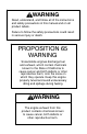
WARNING Read, understand, and follow all of the instructions and safety precautions in this manual and on all product labels. Failure to follow the safety precautions could result in serious injury or death. PROPOSITION 65 WARNING Snowmobile engines discharge fuel and exhaust, which contain chemicals known to the State of California to cause cancer and birth defects or other reproductive harm, onto the snow on which they operate.
Copyright 2004 Polaris Sales Inc. All information contained within this publication is based on the latest product information at the time of publication. Due to constant improvements in the design and quality of production components, some minor discrepancies may result between the actual vehicle and the information presented in this publication. Depictions and/or procedures in this publication are intended for reference use only. No liability can be accepted for omissions or inaccuracies.
WELCOME Thank you for purchasing a Polaris vehicle, and welcome to our world-wide family of Polaris owners. We proudly produce an exciting line of utility and recreational products.
TABLE OF CONTENTS Introduction . . . . . . . . . . . . . . . . . . . . . . . . . . . . . . . 5 This section contains helpful information for owners and drivers and illustrates the location of important identification numbers that should be recorded in the owner’s manual. Safety . . . . . . . . . . . . . . . . . . . . . . . . . . . . . . . . . . . . . 8 This section describes safe vehicle operation and identifies warning decals and their locations. Features . . . . . . . . . . . . . . . . . . . . . . . .
INTRODUCTION Important Notes for Owners and Drivers n After reading this manual, store it in the snowmobile for convenient reference. It should remain with the snowmobile when sold. n The illustrations and photos used in this manual are general representations. Your model may differ. n Follow the maintenance program outlined in this manual. Preventive maintenance ensures that critical components of the snowmobile are inspected by your dealer at specific mileage intervals.
INTRODUCTION Preservation of the Environment Polaris is committed to supporting an environmental education campaign. We encourage state and provincial governments across the snowbelt to adopt rigorous safety training programs that encourage protection of our environment, including wildlife and vegetation. Snowmobile clubs and other organizations are working together to protect our environment.
INTRODUCTION Vehicle Identification Numbers The tunnel vehicle identification number (VIN) and engine serial number are important for model identification when registering your snowmobile, when obtaining insurance, and when ordering replacement parts. In the event your snowmobile is stolen, these numbers are essential to its recovery and identification. Remove the spare key and store it in a safe place. Your key can be duplicated only by mating a Polaris key blank with one of your existing keys.
SAFETY Operator Safety The following signal words and symbols appear throughout this manual and on your vehicle. Your safety is involved when these words and symbols are used. Become familiar with their meanings before reading the manual. The safety alert symbol, on your vehicle or in this manual, alerts you to the potential for personal injury. WARNING The safety alert warning indicates a potential hazard that may result in serious injury or death.
Operator Safety SAFETY Your Polaris snowmobile is a well-engineered and well-constructed recreational vehicle. Follow the recommended maintenance program outlined beginning on page 81 of this manual to ensure that all critical components on the snowmobile are thoroughly inspected by your dealer at specific mileage intervals. WARNING Driving a snowmobile requires your full attention. DO NOT drink alcohol or use drugs or medications before or while driving.
SAFETY Operator Safety Stay Away From Moving Parts WARNING Never hold the snowmobile up or stand behind it while warming up the track. A loose track or flying debris could cause serious personal injury or death. We recommend having your dealer perform track service and alignment procedures. Be alert when riding, and remain properly seated to stay clear of the track. Your snowmobile is propelled by a revolving track that must be partially exposed for proper operation.
Operator Safety SAFETY Survival Preparation For your safety, always ride in a group of other snowmobilers. Always tell someone where you’re going and how long you expect to be gone. If it isn’t possible to ride with others, and you must travel into remote areas, always carry survival equipment that’s appropriate to the conditions you may encounter.
SAFETY Operator Safety Disabled Operators Safe operation of this rider-active vehicle requires good judgement and physical skills. Operators with cognitive or physical disabilities have an increased risk of loss of control, which could result in serious injury or death. Rider Capacity Your Polaris snowmobile is designed for a single rider only. A decal on the console indicates single rider operation. See page 22 for decal location.
Operator Safety SAFETY Driver Awareness Slow down when traveling near poles, posts, or other obstacles. Be especially alert if you’re snowmobiling after dark. Always be on the alert for wire fences. Single strands are especially dangerous, since there may be a great distance between posts. Guy wires on utility poles are also difficult to distinguish. Make sure the way is clear before crossing railroads and other roads and highways.
SAFETY Operator Safety Avalanches Snowmobilers should always be properly trained and equipped before traveling in mountainous terrain: S Take an avalanche class S Travel with experienced people S Travel on designated trails S Make sure each person is equipped with a shovel, probe and avalanche beacon. You don’t have to be snowmobiling on a slope for an avalance to occur. Be aware that all of the snow is connected.
Operator Safety SAFETY Ice and Snow Build-up WARNING Ice and snow build-up may interfere with the steering of your machine, resulting in serious injury or death. Keep the underhood area free of snow and ice. Before driving, manually turn the skis to the left and right to be sure ice and snow are not interfering with full left and right steering. If difficulty is encountered, check for ice and snow build-up that may be obstructing the steering linkage.
SAFETY Operator Safety Driving in Hilly Terrain WARNING Climbing a hill or crossing the face of a slope may result in loss of balance and machine roll-over, causing serious injury or death. Use caution and good judgement when driving in hilly terrain. Operating in hilly terrain requires extreme caution to maintain balance and avoid roll-over. If climbing a hill is unavoidable, keep all your weight low and forward.
Operator Safety SAFETY Clutch Guard Do not operate the engine with the clutch guard removed. The clutch guard is designed to protect the operator from metal parts if the clutch should fail. Although the chance of failure is extremely remote, don’t defeat the purpose of the guard by removing it. It’s provided for your safety. Drive Belt Do not operate the engine with the drive belt removed. Any servicing that requires operation without a belt must be performed by your dealer.
SAFETY Operator Safety Powder Snow Operation Moveable hood closures are included on some Polaris snowmobiles. They are normally left open and are located on the front upper and lower hood openings. If operating in deep snow or in extreme cold conditions (below -20_F), Polaris recommends closing the upper hood closure. WARNING Do not drive for prolonged periods on blacktop, gravel, or ice. Doing so could cause irreversible track damage and lead to serious personal injury.
Operator Safety SAFETY Driving Responsibly Every snowmobile handles differently, and even the most docile conditions may become dangerous if operators drive improperly. If you’re new to snowmobiling, acquaint yourself with the machine and with what it will and won’t do under various conditions. Even seasoned drivers should spend some time getting the feel for a machine before attempting ambitious maneuvers.
SAFETY Operator Safety Windchill/Temperature Charts The following information is provided to help you determine when temperatures become dangerous for riding.
SAFETY Safety Decals and Locations Warning decals have been placed on the snowmobile for your protection. Read and follow the instructions of the decals and other warnings on the snowmobile carefully. If any of the decals depicted in this manual differ from the decals on your snowmobile, always read and follow the instructions of the decals on the snowmobile. If any decal becomes illegible or comes off, contact your Polaris dealer to purchase a replacement.
SAFETY Safety Decals and Locations Track Warning + The track warning decal is on the rear of the tunnel: Stay clear of track. Do not sit on seat back. Entanglement with the track or a fall from seat back may result in severe injury or death. Passenger Warning Some snowmobiles are designed for the operator only, while others are designed for the operator and one passenger. A warning decal on the console indicates whether it’s designed for the operator only (1-Up) or the operator and a passenger (2-Up).
SAFETY Safety Decals and Locations Some Polaris snowmobiles are equipped with reverse. These models will have a reverse warning decal on the lower dash. Reverse Warning Polaris snowmobiles equipped with electronic reverse have this electronic reverse decal: + Reverse operation, even at low speeds, may cause loss of control resulting in serious injury or death. To avoid loss of control, always: S S S S Look behind before and while backing. Avoid sharp turns. Shift to or from reverse only when stopped.
SAFETY Safety Decals and Locations Operation Warning Operation warning decals are present on the console of all Polaris snowmobiles, in both French and English. Operation Warning Decal Text: S To avoid serious injury or death, read and understand all warnings and the Owner’s Manual before operation. If the manual is missing, contact a Polaris dealer for a replacement. S This vehicle is capable of high speeds. Buried objects or uneven terrain can cause loss of control.
FEATURES 4 3 6 5 7 8 2 9 1 10 11 12 15 16 14 13 6 1. 2. 3. 4. 5. 6. 7. 8. Hood Headlight Windshield Handlebar Seat Storage Compartment/Trunk Taillights Rear Bumper 9. 10. 11. 12. 13. 14. 15. 16.
FEATURES Some Polaris snowmobiles are equipped with special features such as a reverse indicator light, electronic fuel gauge, temperature light and electric shock control gauge. Not all models come with these features. Refer to your Owner’s Manual Supplement for the features on your machine. 4 5 6 3 7 8 2 1 1. Fuel Filler Cap (with gauge on some models) 2. Ignition Switch 3. Brake Lever 4. Speedometer 5. Tachometer 6. Engine Stop Switch 7. Throttle Control 8. Hood Hold Down Straps 9.
FEATURES Detonation Elimination Technology (D.E.T.) Some Polaris snowmobiles are equipped with a detonation sensor that monitors the engine and responds to detonation by automatically reducing the engine timing. When activated, the “DETONATION FLASH” indicator (A) will flash in the lower right-hand area of the tachometer. The activated sensor reduces engine detonation by retarding the ignition timing. This results in decreased engine RPM and performance. A D.E.T.
FEATURES Adjustable Seat Bucket 1 2 On models equipped with an adjustable seat bucket (1), the bucket can be adjusted forward or rearward for rider comfort. The seat bucket is removeable for access to the under-seat storage compartment. Do not sit on the seat bucket. Do not operate the snowmobile with the seat bucket removed.
Trunk Lock FEATURES Models equipped with the adjustable seat bucket are also equipped with a trunk lock, which is located between the taillights (1). Use the trunk lock keys to lock or unlock the under-seat storage compartment. If keys are lost or misplaced, see your Polaris dealer. When the trunk is locked, the lock cannot be pressed in and the seat 2 bucket cannot be removed. NOTE: If the trunk is locked after the bucket has been removed, the bucket can still be reinstalled.
THE PERFECT FIT Front Suspension Adjustments Break in the suspension for approximately 150 miles (240 km) and re-grease all suspension parts before making any fine-tuning adjustments. Settings will vary from rider to rider, depending on rider weight, vehicle speed, riding style, and trail conditions. We recommend starting with factory settings and then customizing each adjustment individually to suit rider preference.
THE PERFECT FIT Front Suspension Adjustments WARNING Always verify ski alignment before making adjustments to the IFS. See page 124 to check alignment. If the skis are misaligned, see your dealer, as the camber adjustment may also be affected. For the best ride, the suspension should be adjusted to use the full travel of the shocks with occasional light bottoming.
THE PERFECT FIT Front Suspension Adjustments Shock Damping Adjustments to the compression stiffness of Indy Select or RydeFX SOLO shocks can be made by turning the adjustment screw (Select) or actuator (SOLO), located near the base of the shock (A). This adjustment is the easiest to perform and it should be considered first. A A clockwise adjustment will increase stiffness in both styles of shock, but there are some differences.
THE PERFECT FIT Front Suspension Adjustments Adjusting Front Shock Spring Preload Increasing spring preload will increase ski-to-ground pressure. Decreasing spring preload will decrease ski-to-ground pressure. When adjusting, be sure the springs on both the left and right sides of the machine are at the same adjustment. To increase front shock spring preload, grasp the spring and turn it to the right. Turn it to the left to decrease preload.
THE PERFECT FIT Front Suspension Adjustments Shock Valving RydeFX or RydeFX SOLO shocks can be revalved if spring preload alone isn’t sufficient and further adjustment is desired to control suspension stiffness. WARNING Changing shock valving on RydeFX and RydeFX SOLO shocks requires special tools and a sound knowledge of mechanical theory, tool use, and shop procedures to perform the work safely and correctly. Shocks contain high-pressure nitrogen gas.
THE PERFECT FIT Rear Suspension Adjustments Rider weight, riding style, trail conditions, and vehicle speed all affect suspension action. Each rear suspension can be adjusted to suit rider preference and deliver excellent performance for a given set of conditions. However, all suspension designs and adjustments involve a compromise, or trade-off. For example, a suspension set up for snow-cross racing would provide a very stiff ride on the trail.
THE PERFECT FIT Edge Rear Suspension Adjustments Initial Spring Preload Setting (Sag Method) To set up the EDGE rear suspension torsion spring preload, measure the distance between the ground and rear bumper. This is measurement X. Take the first measurement with no rider and with the rear suspension at full extension. NOTE: X The rear bumper may need to be lifted upward slightly to fully extend the rear suspension.
THE PERFECT FIT Edge Rear Suspension Adjustments Torsion Spring Tension To adjust rear torsion spring tension, rotate the three-position cam using the engine spark plug tool. Different rate torsion springs are available if a firmer ride is desired. Contact your dealer for more information.
THE PERFECT FIT Edge Rear Suspension Adjustments Rear Shocks Indy Select Rear Shock Some snowmobiles are equipped with the Indy Select rear shock, which allows for adjustments to the compression valving by turning the adjustment screw located near the base of the shock. Locate the adjustment screw (A) near the base of the shock. In half-turn increments, turn the screw clockwise to increase compression valving and stiffen the ride, or counterclockwise to reduce compression and soften the ride.
THE PERFECT FIT Edge Rear Suspension Adjustments Rear Shocks Polaris Position Sensitive Shock There are no external adjustments on the Polaris position sensitive (PPS) shock. There is a performance PPS shock kit available for increasing damping, however. If you desire to have the internal valving changed, consult your dealer, or refer to the suspension troubleshooting decal located under the hood or on the clutch guard.
THE PERFECT FIT Edge Rear Suspension Adjustments Suspension Coupling On all Polaris snowmobile rear suspensions, there are two torque arms that control the movement of the rail beam. Prior to the advent of suspension coupling, these torque arms could move independently of each other. Rear suspension coupling links the movement of the front and rear torque arms to each other. There are two types of rear suspension coupling.
THE PERFECT FIT Edge Rear Suspension Adjustments Rear To Front Coupling and the Rear Rear Scissor Stop (RRSS) The rear rear scissor stop (RRSS) couples the movement of the rear torque arm with the front torque arm and limits the amount of independent movement between the rear torque and the front torque arm. Adjusting the RRSS either allows more weight to transfer to the rear for more traction, or allows less weight to transfer to the rear, resulting in improved cornering performance.
THE PERFECT FIT Edge Rear Suspension Adjustments Weight Transfer During Acceleration The preferred method for controlling 1 weight transfer during acceleration of the EDGE rear suspension is by adjusting the rear rear scissor stop (RRSS). The RRSS is located in the best overall trail riding position when delivered from the factory. To decrease weight transfer under acceleration (for improved cornering), rotate the RRSS to a higher position with the scissor stop tool (1) located in your tool kit.
THE PERFECT FIT FAST M-10 Rear Suspension Adjustments The M-10 suspension has been designed to be very sensitive to rider weight. Changes in rider weight of 25 lbs. or more might require appropriate changes in settings. The following information has been compiled to assist you in tuning your M-10 suspension to its maximum potential and achieve the best possible ride. Please take the time to read and understand all the possible adjustments available with the M-10 suspension.
THE PERFECT FIT FAST M-10 Rear Suspension Adjustments Static Sag and Ride Height Settings FRA Position The FRA setting is the primary rear suspension adjustment. It will have the MOST effect on the rear suspension performance. To adjust the FRA: 1. Refer to the initial set-up reference chart (located under the hood of your snowmobile and on page 49) to determine the desired FRA position. 2. To adjust, loosen the hex bolts (A) attaching the rear lower shock cross shaft to the rail beam. 3.
THE PERFECT FIT FAST M-10 Rear Suspension Adjustments Static Sag and Ride Height Settings Rear Spring Preload The top section of the crossover tube (the tube at the top of the rear shock) has a threaded collar on it. The rear spring has a lock tab that fits into the collar to allow easy spring preload adjustment. Refer to the initial set-up chart on page 49. 1.
THE PERFECT FIT FAST M-10 Rear Suspension Adjustments More M-10 Suspension Ride and Performance Settings Overload Spring The overload spring is located inside the main rear spring. Contact is made with this spring only when the crossover tube comes in contact with it toward the end of the travel, which reduces bottoming of the rear suspension. The correct setting of the crossover tube length enables the M-10 suspension to deliver superior performance in “bottoming” situations.
THE PERFECT FIT FAST M-10 Rear Suspension Adjustments Other Ride and Performance Settings Ski Pressure Your M-10 rear suspension ski pressure is set at the factory to deliver the optimum balance between ride and handling. If a rider prefers more ski pressure for improved steering performance, adjustments can be made to the front limiter strap and front arm mount. 4 1. To set the limiter, determine if the rider 3 prefers comfort or control.
THE PERFECT FIT FAST M-10 Rear Suspension Adjustments Other Ride and Performance Settings Track Tension Track adjustment is critical for proper handling. Always maintain correct tension and alignment. Tension adjustments should be made only after the track is warmed up and limber. 1. Turn the machine off. 2. Lift the rear of the Hi-fax machine and safely support it off the ground. 3. Place a 10 lb. weight on the track approximately 16” ahead of the rear axle D C A B to slightly preload the Track track. 4.
THE PERFECT FIT FAST M-10 Rear Suspension Adjustments Initial M-10 Suspension Set-up Chart NOTE: These positions are only preliminary. Experimentation should follow initial set-up to obtain optimum results. Refer to the suspension troubleshooting decal for additional set-up tips. INITIAL SET-UP REFERENCE CHART This chart is a guideline to be used for initial suspension set-ups. Your set-up may vary based on your desired riding style.
THE PERFECT FIT FAST M-10 ACE Suspension Adjustments The FAST M-10 ACE (Adjustable Control Electronics) is a new feature available for some FAST M-10 rear suspensions. It enables a rider to easily adjust the suspension for weight and riding style. The M-10 ACE is an electronically controlled module that replaces the standard M-10 FRA. The ACE changes the rear shock motion ratio by moving the lower shock pivot point a total of 1 1/4 inches, the same amount of adjustment as the standard FRA.
THE PERFECT FIT FAST M-10 ACE Suspension Adjustments M-10 ACE Settings IMPORTANT NOTES: The time to move one position can take up to 12 seconds depending on the rear shock loads. Due to alternator limitations, the ACE module will operate only at engine speeds above 3500 RPM. Similar to the FRA on the standard M-10, the ACE module will have the MOST effect on rear suspension performance.
THE PERFECT FIT FAST M-10 ACE Suspension Adjustments Initial M-10 ACE Set-up Chart These positions are only preliminary. Experimentation should follow initial set-up to obtain optimum results. Refer to the suspension troubleshooting decal for additional set-up tips. NOTE: A INITIAL SET-UP REFERENCE CHART This chart is a guideline to be used for initial suspension set-up. Your set-up may vary based on your desired riding style.
Handlebar Adjustment THE PERFECT FIT Standard Handlebars Follow these steps to adjust the handlebars for a personal fit. 1. Remove the handlebar cover to A expose the handlebar and the four adjuster block bolts (A). 2. Using a 7/16″ (11 mm) wrench, loosen the four nuts on the bottom of the adjuster block (turn handlebar to left or right for access to back nuts). NOTE: It may be necessary to pry the adjuster blocks apart with a screw driver. 3. Adjust the handlebar to the desired height.
THE PERFECT FIT Accessories Polaris offers a wide range of accessories for your snowmobile. From map light to electric start, Polaris has the accessories that will help make each ride more enjoyable. See your dealer for a list of accessories. NOTE: The accessory tether switch is available for all models. Order PN 2870668. Use only Polaris parts and accessories on your Polaris snowmobile.
Accessories THE PERFECT FIT Traction Products Another way to tailor your machine is to install traction products. See your dealer about installing studs and/or carbides. Many tracks with deep lug designs cannot be studded, but your dealer will be able to offer advice and assistance. NOTE: Before equipping your machine with traction products, be aware of the laws in your area pertaining to the use of traction products.
THE PERFECT FIT Accessories Traction Products CAUTION Aggressive studding patterns may require grinding protruding stud bolts flush to prevent idler wheel damage. Maintain track tension on studded tracks on the tight side of the spec to prevent heat exchanger damage. Center of stud must be at least 1 1/8″ (2.86 cm) from outside edge of the track. CAUTION If traction products are added to the track, wear strips must be installed in the tunnel to avoid excessive wear. Never add shims to the wear strip.
THE PERFECT FIT Accessories Wear Strips To avoid excessive tunnel wear, tunnel wear strips must be installed whenever track studding is used. Several wear strips are available. See your dealer for more information. Some models are manufactured with tunnel wear strips or wear strip coolers installed. Wear strips are designed for a specific stud length. See your dealer’s studding chart for recommended traction accessories. Components as viewed from the rear of the track: 1. Top of tunnel 2. Wear strip 3.
PRE-RIDE INSPECTIONS Pre-Ride Checklist Inspect all items on the checklist for proper operation or condition before each use of the snowmobile. Procedures are outlined on the referenced pages. Look for a checkmark (n) on the referenced pages to locate the pre-ride inspection items.
PRE-RIDE INSPECTIONS Before Starting the Engine WARNING Worn, damaged, or malfunctioning components may cause serious injury or death. Before starting the engine, check all components to be sure of proper operation. Read and Understand Your Owner’s Manual Read the Owner’s Manual completely and refer to it often. We’ve attempted to provide as much information as possible to alert you to the safety requirements of snowmobiling.
PRE-RIDE INSPECTIONS Before Starting the Engine n Hydraulic Brakes Properly functioning brakes are critical to your safety. Always check the following items to assure proper operation before starting the engine. A Brake Lever Travel When the brake lever is squeezed, it should move no closer to the handgrip than 1/2″ (1.3 cm) (A). A distance less than this indicates low brake fluid level or air in the hydraulic system. Refer to the brake bleeding information on page 108.
PRE-RIDE INSPECTIONS Before Starting the Engine n Park Brake Lever Lock Your snowmobile may have a park brake lever lock located over the brake lever. Use the brake lever lock only when you want the machine to remain stationary; for example, when parked on an incline for a period of five minutes or less. To apply the lock, squeeze the brake handle and push forward on the brake lever lock. Hold the lock forward and release the brake handle.
PRE-RIDE INSPECTIONS Before Starting the Engine n Check for Proper Operation of Steering System Manually turn the skis completely to the right and to the left. If any difficulty is encountered, check for ice and snow build-up that may be obstructing the steering linkage. Make sure all greasable components are properly lubricated. n Track Inspection WARNING Always inspect the track for damage before using the vehicle.
PRE-RIDE INSPECTIONS Start the Engine and Check n Transmission: Make sure the reverse is not engaged before starting your machine. n Engine Stop Switch: Check the auxiliary shut-off switch for proper operation. Push down to stop the engine. Pull up to release and start the engine. n Tether Switch: If your machine has a tether switch, remove the tether from the switch to ensure the engine stops immediately. Make sure the tether strap is in good condition.
OPERATION Starting the Engine WARNING Before starting the engine, always refer to all safety warnings pertaining to snowmobile operation. Never start your snowmobile without checking all components to be sure of proper operation. See Check Before Starting the Engine beginning on page 59. Starting a Cold Engine (Manual Start) Do not depress the throttle until the engine starts. 1. Turn key to ON. 2. Pull kill switch (shut-off switch) up to RUN. 3. Flip choke toggle to FULL ON. 4.
OPERATION Starting the Engine Starting a Cold Engine (Electric Start) Do not depress the throttle until the engine starts. 1. Flip choke toggle to FULL ON. 2. Pull kill switch (shut-off switch) up to RUN. 3. Turn key to START and crank engine. 4. After the engine starts, release the key to ON and flip the choke toggle to OFF. If the engine slows or wants to stop, use intermittent choking to HALF ON. CHOKE TOGGLE POSITIONS Off Half On On or or or Starting a Warm Engine 1. Turn key to ON. 2.
OPERATION Engine Break-In No single action on your part is as important to long, trouble-free machine life as proper break-in of a new or rebuilt engine. Premix the first tank of gasoline with one pint of Polaris injection oil for each five gallons of fuel. This, in addition to the lubrication supplied by the injection system, will assure proper engine break-in. CAUTION Excessive heat build-up during the first three hours of operation will damage close-fitted engine parts.
OPERATION Engine Break-In Oil Injection System CAUTION Serious engine damage can occur without the proper lubrication. Check the oil tank level often during the first tankful of fuel. If the oil level doesn’t go down, contact your dealer immediately. Always fill the oil reservoir when refueling. Fuel-to-oil mix ratios are controlled by the oil pump and correspond to the engine’s RPM and throttle valve opening.
OPERATION Track Warm-Up WARNING A loose track or flying debris could cause serious personal injury or death. Stand clear of the front of the machine and the moving track. Never hold the snowmobile up or stand behind it while warming up the track. Do not use excessive throttle during warm-up or when the track is free-hanging. Be sure the rear support is stable. WARNING Use of traction products such as studs, ice growsers, etc. will increase the possibility of track damage and/or failure.
Slide Rail and Track Cooling OPERATION CAUTION Inadequate cooling and lubrication will lead to overheating of the slide rail and track, resulting in premature wear and failure. Reduce speeds and frequently drive into fresh snow to allow adequate cooling and polishing of the slide rail and track surfaces. Avoid operating on ice, hard-packed surfaces or roads. Fuel WARNING Gasoline is highly flammable and explosive under certain conditions. S Always exercise extreme caution whenever handling gasoline.
OPERATION Fuel The fuel used in your Polaris engine is as important to engine life and performance as the lubricant used. Your Polaris engine is designed to run on 87 octane non-oxygenated or 89 octane oxygenated pump gasoline. There’s a great deal of variability in the quality of the 87 octane gasoline available across the country, so we encourage the use of premium fuel when possible. Always use the premium fuel switch when using premium fuel. NOTE: Some Polaris snowmobiles require premium gasoline.
Fuel OPERATION Fuel Reserve Capacity (Mechanical Gauge) There are approximately two gallons of fuel left in the tank when the mechanical fuel gauge reads RES. Fuel System Deicers If you use non-oxygenated fuel, Polaris recommends the regular use of isopropyl-based fuel system deicer. Add one to two ounces per gallon (8-16 milliliters per liter) of gasoline to prevent engine damage resulting from fuel system icing and lean fuel mixtures. Never use deicers or additives containing methanol.
OPERATION Oil n Low Oil Indicator Light The low oil indicator light will indicate when to add oil. See page 67 for oil recommendations. When the low oil indicator light is on, oil should be added before further operation of the snowmobile. Visually check the oil level in the bottle. The engine may be operated as long as oil is visible in the oil tank. If oil is not visible, continued operation may cause serious engine damage. Never mix brands of oil.
Carburetion OPERATION Proper carburetor adjustment is critical. A lean mixture (too much air, too little fuel) may result in piston burning, bearing failure, or complete engine failure. A rich mixture (too much fuel, too little air) may foul plugs and cause generally poor engine performance. A lean mixture may be caused by things like fuel line restrictions, foreign matter in the carburetor or clogged fuel filters. A rich mixture may be caused by snow build-up on the pre-filter in the air intake system.
OPERATION n Engine Stop Switch Push down on the engine stop switch (A) to stop the engine in an emergency. This will ground out the ignition and bring the engine to a quick stop. To restart the engine, the switch must be pulled up to the ON position. A n Throttle Safety Switch B Test the throttle safety switch system daily before operation.
Throttle Lever OPERATION WARNING An improperly functioning throttle lever may cause erratic machine behavior and loss of control, which could result in serious injury or death. If the throttle lever does not work properly, DO NOT start the engine. If the engine stops abruptly when the throttle lever is released: 1. Turn the ignition switch to OFF. 2. Visually inspect the throttle cable and carburetor(s) to determine what caused the safety switch to activate. 3.
OPERATION Emergency Stopping The following chart lists methods for stopping the snowmobile in the event of an emergency. See page 74 for more information about the engine stop switch and throttle safety switch.
Emergency Starting OPERATION Your machine is equipped with a tool kit containing essential tools for emergency use. Machine’s equipped with electric start have a recoil for emergency starting. On non-electric start models, if the recoil starter system fails, an emergency start strap is provided in the kit. WARNING Serious injury can result from wrapping the start strap around your hand while using the emergency starting procedure. DO NOT wrap the start strap around your hand.
OPERATION Reverse Operation WARNING Improper reverse operation, even at low speeds, may cause loss of control, resulting in serious injury or death. S Always look behind the vehicle before and while backing. S Always avoid sharp turns. S Shift to or from reverse only when stopped. S Always apply throttle slowly. Mechanical Reverse Make sure the shift lever is shifted completely into forward or reverse position.
Reverse Operation OPERATION Electronic Reverse (PERCt) Electronic reverse will activate only if the engine is below 4000 RPM. If your machine is running at an altitude of over 6000 feet, adjust the ignition setting as described below. Always make sure the vehicle is stopped and the engine is running at idle before shifting to reverse. 1. Make sure the area behind your vehicle is clear. 2. Push the yellow reverse button on the left-hand control for one second, then release.
OPERATION Daily Storage At the end of each ride, park the snowmobile on a level surface and support it at the rear with an appropriate track stand. The track should be suspended approximately 4″ (20 cm) off the ground. Remove the key and cover the machine. NOTE: Polaris has accessory covers and track stands available to fit all models. See your dealer for more information.
MAINTENANCE Polaris Recommended Maintenance Program To ensure many trouble-free miles of snowmobiling enjoyment, follow recommended regular maintenance and perform service checks as outlined in this manual. The recommended maintenance schedule on your snowmobile calls for service and maintenance inspections at 150 miles (240 km), 500 miles (800 km) and 1000 miles (1600 km). These inspections should be performed by a qualified service technician.
MAINTENANCE Periodic Maintenance Interval Table The following chart is a guide based on average riding conditions. You may need to increase frequency based on riding conditions. When inspection reveals the need for replacement parts, always use genuine Polaris parts, available from your Polaris dealer. Item See Page P Frequency 150 mi. (240 km) 500 mi. (800 km) 1000 mi. (1600 km) 2000 mi.
MAINTENANCE Periodic Maintenance Interval Table Item See Page P Frequency 150 mi. (240 km) 500 mi. (800 km) 1000 mi. (1600 km) 2000 mi.
MAINTENANCE Periodic Maintenance Interval Table Item See Page P Frequency 150 mi. (240 km) 500 mi. (800 km) 1000 mi. (1600 km) 2000 mi.
MAINTENANCE Maintenance Log Present this section of your manual to your dealer each time your snowmobile is serviced. This will provide you and future owners with an accurate log of maintenance and services performed on the snowmobile.
MAINTENANCE Maintenance Log Additional Services Performed Authorized Polaris Servicing Dealer Servicing Technician Date Mileage Type of Service Additional Services Performed Authorized Polaris Servicing Dealer Servicing Technician Date Type of Service 86 Mileage
MAINTENANCE Lubrication Lubricate the suspension and steering components with Polaris Premium All-Season Grease at 500 miles (800 km) and annually or every 1000 miles (1600 km) thereafter. See page 134 for the part numbers of Polaris products. The illustration shows the location of suspension and steering components. A + indicates a grease point or fitting. S Grease the left and right spindles. Raise the front end of the machine to permit better grease entry into the spindle area.
MAINTENANCE Lubrication The suspension pivot shafts should be lubricated with Polaris Premium All Season Grease at 500 miles (800 km) initially, every 1000 miles (1600 km) after that, and before off-season storage each year. Lack of lubrication will adversely affect your ride and the life of the suspension. For detailed information about suspension lubrication and adjustments, see your Polaris dealer. NOTE: The following illustrations are general representations. Your model may differ.
MAINTENANCE Lubrication L L L L L L L L L L L L L L L L 89
MAINTENANCE Lubrication Suspension Lubrication - EDGE L L L L L Suspension Lubrication - M-10 ACE L L L 90
Lubrication Jackshaft Bearing Greasing MAINTENANCE + + Loosen the driven clutch retaining bolt and pull the clutch outward to expose the bearing and grease fitting. Inject grease into the grease fitting in the flangette until grease purges from inside or outside the bearing seal (may take only two pumps). Push the clutch back onto the shaft and replace the clutch retaining bolt. Torque to 18 ft. lbs. (24.4 Nm).
MAINTENANCE Lubrication n Chaincase Oil Level It’s the operator’s responsibility to check and maintain the proper chaincase oil level. To check the oil level, place the machine on a level surface. The oil level should be between the “safe” marks on the dipstick (A). Add Polaris synthetic chaincase oil through the dipstick opening. Do not overfill. See page 134 for the part numbers of Polaris products. Flush the chaincase after the first 500 miles (800 km), then every 1000 miles (1600 km) or seasonally.
General Maintenance MAINTENANCE Spark Plugs It’s very important to use the correct spark plug for your machine. A spark plug with a heat range too high will cause engine damage. A spark plug with a heat range too low will cause excessive fouling and engine malfunctioning.
MAINTENANCE General Maintenance Spark Plugs Spark plug condition is indicative of engine operation. The spark plug firing end condition should be read after the engine has been warmed up and the vehicle has been driven at higher speeds. Immediately check the spark plug for correct color. WARNING A hot exhaust system and engine can cause serious burns. Wear protective gloves when removing a spark plug for inspection.
General Maintenance MAINTENANCE Intake Filter The intake foam filter limits snow ingestion into the intake system. When operating in loose powder snow, check the top of the foam filter periodically to remove any accumulation of snow. CAUTION Operating the snowmobile with the intake filters removed may cause carburetor icing. The result will be poor fuel economy or carburetor malfunction. Always reinstall the intake filters before operating the snowmobile.
MAINTENANCE General Maintenance Water Pump Belt Inspection Some liquid cooled models require inspection of the water pump belt at 1500 miles (2400 km). Inspect belt width (A) and condition, and replace if cracked or worn past the width service limit (.250″ / 6.35mm). New belt width is approximately .345″ (8.75 mm). See your Polaris dealer if the belt needs to be replaced.
General Maintenance MAINTENANCE Water/Sediment Trap Service Most Polaris snowmobiles contain patented carburetor bowl water/sediment traps located at the bottom of each carburetor. The trap, consisting of a hose with a plug, should be drained at least every 2000 miles (3200 km) and inspected for contamination. WARNING When draining the traps, fuel spillage will occur.
MAINTENANCE General Maintenance Fuel Filter/Fuel Lines See your Polaris dealer for replacement of the in-tank fuel filter (1) every 1000 miles (or annually). Inspect the fuel lines regularly for signs of deterioration or damage. Always check fuel line condition after periods of storage. Normal deterioration from weather and fuel 1 compounds may occur. Replace worn or damaged fuel lines promptly.
General Maintenance MAINTENANCE General Carburetor Information The number stamped in the end of the main jet indicates the jet size. The jet installed at the time of manufacture is not necessarily correct for your elevation. It’s your dealer’s responsibility to make sure the correct main jet is installed. CAUTION Operating the snowmobile with incorrect jetting can result in serious engine damage. Have your Polaris dealer perform all carburetor adjustments to ensure all adjustments are done correctly.
MAINTENANCE General Maintenance Exhaust System Check the exhaust system for wear or damage at approximately 2000 miles (3200 km). To inspect, allow the engine and exhaust system to cool completely. Open the hood and inspect the muffler and pipes for cracks or damage. Check for weak or missing retaining springs or damper/support grommets. WARNING Hot exhaust system parts can cause serious burns. Allow adequate time for the exhaust system to cool. Never perform this procedure with the engine running.
General Maintenance MAINTENANCE Coolant Mixture The coolant supplied in the system is a 50/50 mixture of ethylene-glycol and distilled water. This mixture provides protection against freezing at temperatures to -34° F (-37° C). If greater protection is required, the percentage of antifreeze to water may be increased. Use Premium 60/40 anti-freeze coolant, which is already premixed and ready to use. Do not dilute with water. Never exceed a 60% antifreeze/40% water mixture.
MAINTENANCE General Maintenance Coolant Level The engine coolant level is controlled by the recovery system. The recovery system components are: S Coolant bottle or overflow tank S Engine filler neck S Pressure cap (on some models) S Connecting hoses Flushing the Cooling System To ensure that the coolant maintains its ability to protect the engine, the system should be completely drained every two years and a fresh mixture of antifreeze and distilled water should be added.
General Maintenance MAINTENANCE Bleeding the Cooling System CAUTION If coolant flow becomes restricted or plugged, coolant loss, air lock or engine damage may result. Most cooling systems are equipped with a filter that should be periodically inspected or replaced. 1. Remove the pressure cap and fill the coolant bottle with properly mixed coolant to the maximum mark. 2. Elevate the front end of the machine slightly to aid in bleeding of the heat exchangers. 3.
MAINTENANCE General Maintenance Drive Chain Tension Check drive chain tension weekly and before each long trip. To obtain correct chain tension: 1. Rotate the driven clutch counterclockwise to move all chain slack to the tensioner side. Lock the brake lever lock, or have an assistant hold the brake lever firmly. 2. Loosen the adjuster bolt jam nut (A). 3. Finger tighten the adjuster bolt (B) until it can no longer be adjusted by hand, then back off 1/4 turn. 4.
General Maintenance n Hydraulic Brake Inspection MAINTENANCE Inspect the brake lever reserve before each use of the snowmobile. A Firmly depress the brake lever and measure the clearance between the lever and handlebar grip. This distance, called brake lever reserve (A), should be no less than 1/2″ (1.3 cm). Brake pads must be replaced when the brake pad material becomes thinner than the backing plate (approximately 1/16″). A kit is available for replacing brake pads. See your dealer.
MAINTENANCE General Maintenance Brake Components 1 2 5 4 3 1. 2. 3. 4. 5. Brake Caliper Chaincase Brake Disc Backing Plate Brake Pad Material (Replace when thickness is less than 1/16″). Excessive Lever Travel Hydraulic brakes are self-adjusting, but if excessive brake pad clearance develops, as described on page 105, the machine should be returned to an authorized Polaris dealer for inspection and adjustment.
General Maintenance MAINTENANCE Brake Fluid WARNING After opening a bottle of brake fluid, always discard any unused portion. Never store or use a partial bottle. Brake fluid is hygroscopic, meaning it rapidly absorbs moisture from the air. The moisture causes the boiling temperature of the brake fluid to drop, which can lead to early brake fade and the possibility of accident or severe injury. WARNING Keep the master cylinder cover free of dirt and debris.
MAINTENANCE General Maintenance Bleeding the Hydraulic Brake System Air in the hydraulic brake system will cause spongy brake lever action. Bleed the system before operating the snowmobile. WARNING Operating the vehicle with a spongy brake lever can result in loss of brakes, which could cause an accident and lead to serious injury or death. Never operate the vehicle with a spongy-feeling brake lever. During the bleeding procedure, keep the brake handle as level as possible.
General Maintenance MAINTENANCE Headlight Adjustment The headlight may be adjusted for vertical aim using the following procedure: 1. Place the snowmobile on a level surface with the headlight approximately 25 feet (7.6m) from a wall. 2. Measure the distance from the floor to the center of the headlight and make a mark on the wall. 3. Start the engine and turn the headlight switch to high beam. 4. Observe the headlight aim. The most intense part of the headlight beam should be aimed 2″ (5.
MAINTENANCE General Maintenance NOTE: Do not touch a halogen bulb with bare fingers. Oil from skin leaves a residue, causing a hot spot that will shorten the life of the lamp. Removing Halogen Bulbs 1. Pinch the ends of the spring (1) together and lift until it releases 2 from the spring retainer. 2. Lift the spring carefully around the wire harness (2) and flip it to 3 the outside of the housing. 3. With the wire harness attached 1 to the bulb (3), withdraw the bulb from the housing. 4.
General Maintenance MAINTENANCE Taillight/Brakelight Replacement To replace a bulb on most Edge models, remove the taillight lens screws and remove the lens to access the bulbs. On models with the adjustable seat bucket: 1. Remove the two sets of fasteners (1) at the rear corners of the seat base. 2. Tilt the rear of the seat upward to access the bulbs from under the seat. 3. Twist the bulb socket slightly and pull it from the assembly. 1 4. Replace the bulb and reinstall the socket into the assembly. 5.
MAINTENANCE General Maintenance Clutch System WARNING If you become aware of higher than normal clutch engagement or an unusual vibration or shift pattern, see your dealer immediately. Do not operate the machine until repairs have been made. All clutch maintenance and repairs must be performed by an authorized Polaris dealer. Any unauthorized modifications to clutches, such as adding or removing weights, will void the warranty.
General Maintenance n Drive Belt Condition MAINTENANCE Periodically check the condition and tension of the drive belt, and always carry a spare. Inspect the belt for signs of excessive wear: frayed edges, missing cogs, cracks and excessive looseness. Replace the belt if any of these conditions exist. For improved drive-away during extremely cold temperatures, remove the belt and warm it to room temperature. Reinstall it before starting the snowmobile.
MAINTENANCE General Maintenance Drive Belt Installation 1. Drop the drive belt over the drive clutch and pull back the slack (A). NOTE: To ensure satisfactory belt life, install belts so they operate in the same direction of rotation by positioning the identification numbers so that you can read them. If required, separate the sheaves as outlined in the belt removal procedures. A B 2. Turn the driven clutch moveable sheave clockwise while pushing inward and forcing the belt down between the sheaves.
General Maintenance n Drive Belt Deflection Measure belt deflection with both clutches at rest and in their full neutral position. Place a straight edge on the belt (A) and apply downward pressure while measuring at point B. This measurement should be 1 1/4”. MAINTENANCE A B Drive Belt Adjustment Standard Clutch Belt deflection can be adjusted without removing the clutch from the jackshaft. 1. Pull the belt into the driven clutch to slightly open the sheaves. 2.
MAINTENANCE General Maintenance Torque Stop If your snowmobile is equipped with an engine torque stop (1), periodically check torque stop clearance. With clutches in proper alignment, the torque stop clearance should be a minimum of .010″ to a maximum of .030″ from the engine case (2). Adjust if necessary, and lock the jam nut.
General Maintenance MAINTENANCE Tool Kit A tool kit is included with each 1 machine for emergency and routine maintenance. Your tool kit will contain only the tools applicable to your model. 1. Emergency Start Strap 4 (manual start models) 5 2. Phillips Screwdriver 3. Tubular Socket 4. Tubular Socket Handle 5. Wrench 6 6. Flat Screwdriver 7. Scissor Stop Wrench (Edge Models) 8. Adjuster Wrench (M-10 Models) 9. Box End Wrench 9 Always keep the tool kit with the snowmobile.
MAINTENANCE General Maintenance Fall Tune-Up For maximum performance, arrange for a fall service tune-up with your Polaris dealer. His experienced and trained service technician will keep your machine in peak operating condition. Maintenance Items The tools and maintenance items mentioned in this book, as well as a long line of other Polaris accessories, are available at your Polaris dealer.
Track Maintenance MAINTENANCE Track Inspection WARNING Broken track rods are a serious safety hazard. They can cause a rotating track to come off the machine, which could cause serious injury or death. Never operate with a damaged track. Never rotate a damaged track under power. 21 3 Using a hoist, safely lift and support the 1 2 rear of the snowmobile off the ground. Rotate the track by hand to check for possible damage.
MAINTENANCE Track Maintenance WARNING Moving parts can cut and crush body parts. When performing the checks and adjustments recommended on the following pages, stay clear of all moving parts. Never perform track measurement or adjustments with the engine running. Track Tension Track adjustment is critical for proper handling. Always maintain correct tension and alignment. Tension adjustments should be made only after the track is warmed up and limber. 1. Turn the machine off. 2.
MAINTENANCE Track Maintenance Track Tension If the track needs adjustment: 5. Loosen the rear idler shaft bolt (D). 6. Loosen the locknuts (A). 7. Tighten or loosen the track adjusting screws (B) as necessary to provide equal adjustment on both sides of the track. 8. Repeat the measurement on the other side of the track. NOTE: Hi-fax B A Weight C D Track Check more frequently when the machine is new. 9. Start the machine and slowly rotate the track at least five revolutions.
MAINTENANCE Track Maintenance n Track Alignment Periodically check that the track is centered and running evenly on the slide rails. Misalignment will cause excessive wear to the track and slide rail. 1. Safely support the rear of the machine with the track off the ground. 2. Start the engine and apply a small amount of throttle until the track turns slowly at least five complete revolutions. Stop the engine and A let the track come to a stop (do not apply brakes). 3.
MAINTENANCE Steering System Steering Inspection and Adjustment Each week, or before a long ride, check fasteners and tighten if necessary. Specific fasteners that should be checked are marked with a + in the illustration.
MAINTENANCE Steering System Ski Alignment WARNING Improper ski alignment or adjustment may cause loss of steering control, resulting in serious injury or death. Do not attempt to change the ski alignment or camber adjustment. See your Polaris dealer. With the handlebars in a straight ahead position, and with vehicle weight compressing the suspension, measure from the straight edge of the skis at the center of the ski mounting bolt.
MAINTENANCE Steering System n Ski Skags WARNING Worn skis and/or skags will adversely affect handling. Loss of vehicle control may result, causing serious injury or death. See your dealer’s studding chart for recommended skags. If you install longer or more aggressive carbide skags than the original equipment, it may also be necessary to add track studs to maintain proper vehicle control while turning on hard-packed snow or ice.
MAINTENANCE Suspension Maintenance n Hi-Fax Wear Check Hi-fax wear by measuring the thickness at several points along the rail (A). Replace Hi-fax when a thickness of 7/16″ (1.1 cm) is reached. Take the machine to your dealer for Hi-fax replacement. A A 7/16″ (1.
Suspension Maintenance MAINTENANCE Loose nuts and bolts can reduce your snowmobile’s reliability and cause needless repairs and down time. Before beginning any snowmobile trip, a visual inspection will uncover potential problems. Check the following items on a weekly basis or before any long trip: n Check suspension mounting bolts for tightness. n Check rear idler wheel bolts for tightness. See page 121 for torque specs. n Check rear idler adjusting bolt locknuts for tightness.
MAINTENANCE Extended Storage Bearings Grease the jackshaft and drive shaft clutch side bearings with Polaris Premium All-Season Grease or a similar high quality grease to prevent corrosion. See page 134 for part numbers. Clutch and Drive System Remove the drive belt and store in a cool dry location. Lubricate the sheave faces of the drive and driven clutches with a light coat of oil or Polaris Cable Lubricant. See page 134 for part numbers.
Extended Storage MAINTENANCE Engine and Carburetor Protection Using a fuel stabilizer and topping off the fuel tank eliminates the need to drain the fuel system. If you prefer to drain the fuel tank, use the following procedure: 1. Transfer unused fuel from the fuel tank to an approved fuel container using a siphon pump. Do not re-use fuel after storage. 2. Securely support the front of the snowmobile with a jack stand so the machine is elevated and the engine is tilted rearward. 3.
MAINTENANCE Extended Storage Track and Suspension Moderate track tension should be maintained during summer storage. The machine should be supported off the ground to allow the track to hang freely. See illustration. Transporting the Snowmobile Whenever the snowmobile is transported: 1. Turn the fuel valve clockwise to OFF to shut off the fuel supply (1). Turn the valve counter-clockwise to ON to turn the fuel supply on (2). NOTE: The fuel valve is located under the hood of your machine. 2.
Battery MAINTENANCE Battery Fluid WARNING Battery electrolyte is poisonous. It contains acid! Serious burns can result from contact with the skin, eyes, or clothing. If contact occurs, seek immediate medical attention. KEEP OUT OF REACH OF CHILDREN. EXTERNAL: Flush with water. INTERNAL: Drink large quantities of water or milk. Call physician immediately. EYES: Flush with water for 15 minutes and get prompt medical attention. Batteries produce explosive gases. Keep sparks, open flames, cigarettes, etc.
MAINTENANCE Battery Battery Connections Keep battery terminals and connections free of corrosion. When cleaning is necessary, remove the corrosion with a stiff wire brush. Wash terminals and connections with a solution of one tablespoon baking soda and one cup water. Rinse well with tap water and dry with clean shop towels. Coat the terminals with dielectric grease or petroleum jelly. CAUTION Tap water contains minerals that will damage a battery and shorten its life.
MAINTENANCE Battery Battery Installation WARNING Batteries contain gases that can explode. If the battery vent tube is pinched or kinked, battery gases could accumulate. Whenever removing or installing the battery, disconnect the negative (black) cable first and reinstall the negative cable last to avoid the possibility of explosion. Battery electrolyte contains acid. Avoid skin contact with electrolyte as severe burns may result. 1. Place the battery in its holder. Attach the hold down strap. 2.
POLARIS PRODUCTS Part No. Description Engine Lubricants 2870791 Fogging Oil (12 oz. Aerosol) 2871098 Premium 2-Cycle Engine Oil (qt.) 2871097 Premium 2-Cycle Engine Oil (gal.) 2871240 Premium 2-Cycle Engine Oil (2.5 gal.) 2871721 Premium Gold Synthetic 2-Cycle Engine Oil (qt.) 2871722 Premium Gold Synthetic 2-Cycle Engine Oil (gal.) 2872347 Premium Gold Synthetic 2-Cycle Engine Oil (2.5 gal.) 2874438 VES II Synthetic 2-Cycle Engine Oil (qt.
TROUBLESHOOTING Engine Troubleshooting CAUTION: Unless you have experience and training in two-cycle engine repair, see your dealer if technical problems arise. Problem Probable Cause Solution Erratic engine operating RPM during acceleration or load variations Drive clutch binding -Disassemble drive clutch to inspect shift weights for wear and free operation. SEE YOUR DEALER. -Clean and polish stationary shaft hub. Driven clutch malfunction -Replace ramp buttons and rollers. SEE YOUR DEALER.
TROUBLESHOOTING Engine Troubleshooting Problem Noise in drive system Probable Cause Solution Broken drive clutch components -SEE YOUR DEALER. Bearing failure/ chaincase, jackshaft, or front drive shaft -SEE YOUR DEALER. Drive belt surface flat spots -Inspect and replace if necessary. Drive chain loose or worn, sprocket teeth broken -Inspect and adjust or replace. Worn drive belt -Inspect and replace if necessary. Excessive belt/sheave clearance -SEE YOUR DEALER.
TROUBLESHOOTING Engine Troubleshooting Problem Engine turns but fails to start Probable Cause Solution Faulty ignition -Remove spark plug(s) and replace with new plug(s). If engine still fails to start, check for spark; if no spark SEE YOUR DEALER. No fuel to engine -Make sure the fuel valve is “ON”. Check tank level and fill up with correct fuel. -Ice in fuel line, filter, or pump. On the standard Polaris carburetor, the choke will not function with the throttle depressed.
TROUBLESHOOTING Edge Suspension Troubleshooting Problem Solution (perform only one change at a time) Rear suspension bottoms too easily -Increase torsion spring preload -Increase rear shock compression damping by turning screw clockwise -Increase torsion spring wire diameter (see your dealer) Rides too stiff in rear -Check for binding suspension shafts and grease all pivot points -Decrease torsion spring preload adjustments -Decrease rear shock compression valving by turning screw counterclockwise (if
TROUBLESHOOTING M-10 Suspension Troubleshooting Problem Solution (perform only one change at a time) Rear suspension bottoms too easily - Increase FRA position (see setup decal under hood for initial position - Increase X-over tube length (see setup decal under hood) - Increase rear track shock coil spring preload - Increase front track shock coil spring preload - Change to optional stiff rear track shock compression spring (see your dealer) - Revalve rear track shock compression damping (see your deale
TROUBLESHOOTING M-10 ACE Suspension Troubleshooting Problem Solution (perform only one change at a time) Rear suspension bottoms too easily - Increase M-10 ACE position (see setup decal under hood for initial position) - Increase rear track shock coil spring preload - Revalve rear track shock compression damping (see your dealer) - Check track tension Rides too stiff in rear - Decrease M-10 ACE position (see setup decal under hood) - Decrease rear track shock spring preload collar spacing - Revalve re
Belt Troubleshooting TROUBLESHOOTING Belt Wear/Burn Diagnosis Causes Solutions Driving at low RPM Drive at higher RPMs. Gear the machine down. Check belt deflection. Insufficient warm-up Warm the engine at least five minutes. Take the drive belt off the machine in extremely cold weather and warm it up. Break machine loose from the snow. Towing at low RPM Do not tow in deep snow. Use fast, aggressive throttle to engage clutch.
WARRANTY Service And Warranty Information Obtaining Service and Warranty Assistance Read and understand the service data and the Polaris warranty information contained in this manual. Contact your Polaris dealer for replacement parts, service or warranty. Your dealer receives frequent updates on changes, modifications and tips on snowmobile maintenance, which may supersede information contained in this manual.
Limited Warranty WARRANTY Polaris Sales Inc., 2100 Highway 55, Medina, MN 55340, provides a ONE YEAR LIMITED WARRANTY on all components of the Polaris snowmobile against defects in material or workmanship. This warranty covers the parts and labor charges for repair or replacement of defective parts that are covered by this warranty. The warranty begins on the date of purchase. This warranty is transferrable to another consumer, during the warranty period, through a Polaris dealer.
WARRANTY Limitations of warranties and remedies ALL IMPLIED WARRANTIES (INCLUDING BUT NOT LIMITED TO THE IMPLIED WARRANTIES OF MERCHANTABILITY AND FITNESS FOR A PARTICULAR PURPOSE) ARE LIMITED IN DURATION TO THE ABOVE ONE YEAR WARRANTY PERIOD. POLARIS FURTHER DISCLAIMS ALL EXPRESS WARRANTIES NOT STATED IN THIS WARRANTY. Some states do not allow limitations on how long an implied warranty lasts, so the above limitation may not apply to you if inconsistent with controlling state law.
WARRANTY Conditions and Exclusions In order to qualify for warranty, the product must have been properly set up and tested by a Polaris Dealer (if applicable). Failure of any dealer to perform the required vehicle Pre-Delivery Inspection, perform all applicable service bulletins and have the consumer sign the PDI form prior to delivery may void the warranty. Failure to provide proof of required periodic maintenance upon request may result in denial of warranty coverage.
WARRANTY Polaris Second Year Engine Service Contract Second Year Engine Service Contract is standard on all eligible new and unused snowmobiles that were Snow Checked through an authorized Polaris dealer during the March/April Snow Check promotion. The free Second Year Engine Service Contract is honored by all authorized Polaris snowmobile dealers in North America and is transferable 120 days after the original purchase date, free of charge, through any Polaris snowmobile dealer.
Exported Vehicles WARRANTY EXCEPT WHERE SPECIFICALLY REQUIRED BY LAW, THERE IS NO WARRANTY OR SERVICE BULLETIN COVERAGE ON THIS VEHICLE IF IT IS SOLD OUTSIDE THE COUNTRY OF THE SELLING DEALER’S AUTHORIZED LOCATION. This policy does not apply to vehicles that have received authorization for export from Polaris Industries. Dealers may not give authorization for export. You should consult an authorized dealer to determine this vehicle’s warranty or service bulletin coverage if you have any questions.
INDEX A D Accessories . . . . . . . . . . . . . . . . . . . 54-57 Airbox . . . . . . . . . . . . . . . . . . . . . . . . . 21 Avalanches . . . . . . . . . . . . . . . . . . . . . . 14 D.E.T. Flash Signals . . . . . . . . . . . . . . . 27 D.E.T. Troubleshooting . . . . . . . . . . . . 27 Daily Storage . . . . . . . . . . . . . . . . . . . . 80 Detonation Elimination Technology . . 27 Disabled Operators . . . . . . . . . . . . . . . . 12 Drive Belt . . . . . . . . . . . . . . . . . . . . . . .
INDEX H P Halogen Bulbs . . . . . . . . . . . . . . . . . . 110 Handlebar Adjustment . . . . . . . . . . . . . 53 Handlebars, Standard . . . . . . . . . . . . . . 53 Headlight Adjustment . . . . . . . . . . . . 109 Hi-Fax Wear . . . . . . . . . . . . . . . . . . . . 126 High Temperature Indicator . . . . . . . . 101 Hydraulic Brake Inspection . . . . . . . . 105 Passenger . . . . . . . . . . . . . . . . . . . . . . . 22 PERC . . . . . . . . . . . . . . . . . . . . . . . . . . 79 Plug Cleaning . . . . . .
INDEX S T Ski Skags . . . . . . . . . . . . . . . . . . . . . . 125 Slide Rail and Track Cooling . . . . . . . . 69 Spark Plugs . . . . . . . . . . . . . . . . . . . 93-94 Spring Preload, Edge . . . . . . . . . . . . . . 36 Start the Engine and Check . . . . . . . . . 63 Starting a Cold Engine . . . . . . . . . . 64-65 Starting a Warm Engine . . . . . . . . . . . . 65 Starting the Engine . . . . . . . . . . . . . . . . 64 Starting, Emergency . . . . . . . . . . . . . . . 77 Steering Adjustment . . . . . .