INSTALLATION & OWNER’S MANUAL Rev. K, p. 1 of 11 POLARIS FREEDOM CAB INSTALLATION INSTRUCTIONS FOR THE POLARIS RANGER (p/n 2876196-067) IMPORTANT: THIS ACCESSORY WEIGHS 340 POUNDS. PLEASE ADJUST THE VEHICLE PAYLOAD ACCORDINGLY. The contents of this manual are the property of the owner. Be sure to leave with the owner when installation is complete. Standard item with purchase of cab: one driver’s side wiper. Optional accessories available: passenger’s side wiper, work lights, and strobe light.
Rev. K, p. 2 of 11 DESIGN CONCEPT Curtis Cabs feature an assembly of parts designed for your vehicle which require adjustment and alignment of components to accommodate vehicle variations and provide proper weather protection. For accurate installation, proper operation, and years of satisfaction, please read and understand the installation instructions. From all of us at Curtis, we thank you for choosing our product. GENERAL INFORMATION Helpful Reminders: A. B. C. D.
Rev. K, p. 3 of 11 WARNING! Gasoline—Flammable! Explosive! Do not operate gasoline vehicle in an enclosed area without proper ventilation. The engine produces carbon monoxide, which is an odorless, deadly poison. This vehicle and enclosure will not provide protection from rollover, flying objects, lightening, or other hazards. If caught in a storm, exit the vehicle and seek shelter in accordance with applicable safety guidelines for your location.
Rev. K, p. 4 of 11 1. VEHICLE PREP. 1.1 Using a T27 Torx bit, remove three (3) original equipment screws on each side of the vehicle floorboard as shown in fig. 1.1. Save these six (6) bolts for reinstallation in step 3.3. Note: these are self-tapping screws that were factory installed. Use care when removing and re-installing to avoid cross-threading or damaging the female threads underneath the vehicle floorboard. 2. “P” CLAMPS 2.1 Install a total of seven (7) “P” clamps as follows: per fig. 2.
Rev. K, p. 5 of 11 3. SIDE FRAME & DOOR ASS’Y. (cont’d.) 3.2 Carefully open the door to the midway or slightly beyond position to gain access for installing the hip restraint bracket. Insert the tongue of the bracket as shown in fig. 3.2 and rotate the bracket up and install one 5/1618 x 1” long hex head bolt, one internal tooth locking washer, and one flat steel washer into the factory installed weld nut. Leave bolt loose. 3.
Rev. K, p. 6 of 11 6. TIGHTEN ALL BOLTS flat portion towards the ground 6.1 Tighten all cab bolts at this time. Reminder: do not over-tighten the six (6) self-tapping floorboard screws. 6.2 Use a small bar clamp to hold the side frame against the top side tubular frame. Using a drill and a Phillips head bit, install two self-drilling and self-tapping screws through the “P” clamps and into the underside of the side frame tubing as shown in figure 6.2. Do not over-torque these screws.
Rev. K, p. 7 of 11 8. ROOF & CONSOLE ASS’Y. (cont.) 8.3 A driver’s side wiper is provided. Place the driver’s side wiper wire below the front tubular frame as shown in fig. 8.3. If installing an optional passenger’s side wiper, place that wire below the front tubular frame as well. If not installing a passenger’s side wiper, push the passenger’s side wiring up into the console to hide it.
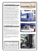
Rev. K, p. 8 of 11 this end towards the ground 9 GAS SHOCKS AND WIRING 9.1 Open the windshield and attach the two gas shocks as shown in fig. 9.1 with the rod end of the gas shock pointing down. Snap the gas shock onto the ball studs. Leave the windshield in the open position. 9.2 Run the loomed battery wires over the front tubular frame, down along the side tubular frame and into the gap behind the hood as shown in fig. 9.2.
Rev. K, p. 9 of 11 CARE AND MAINTENANCE (IMPORTANT: be sure to leave this page with the owner once installation is complete. Check and tighten hardware after 40 hours of operation. Periodically inspect and tighten hardware for the remainder of the unit’s service life. IMPORTANT CLEANING INFORMATION Keep the enclosure components clean in order to prevent dust and dirt from forming an unattractive film.