
Specification

POLARIS™
Pre-Insulated Connectors
Max Ampacity
NSi Industries LLC
800.321.5847
www.nsiindustries.com
SIZE OF
CONNECTOR
# OF
PARALLEL
CONDUCTORS
# OF
CONNECTOR
WIRE PORTS
COPPER
CONDUCTOR
(AMPS)
ALUMINUM
CONDUCTOR
(AMPS)
250
2 4 527 410
250
3 6 790 615
250
4 8 1053 820
350
2 4 657 514
350
3 6 985 770
350
4 8 1314 1028
500
2 4 806 631
500
3 6 1209 946
500
4 8 1612 1262
600
2 4 1035 810
600
3 6 1554 1215
600
4 8 2070 1620
750
2 4 1178 930
750
3 6 1767 1395
750
4 8 2356 1860
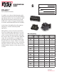
To enable users to achieve desired ampacity with a
UL listed pre-insulated connector through paralleling,
NSi Industries’ Polaris
™
line of connectors have been
fully tested and meet the specifications for UL 486
A/B for 90°C conductor (copper and aluminum) in
accordance with the National Electrical Code (NEC).
See the chart to the right that shows the maximum
ampacity for connectors utilized in parallel
applications.
Although these connectors have been tested in the
worst case condition (Line conductor(s) on one end
of the connector and load conductor(s) on opposite
end of connector), laboratory tests have shown that
the connector will run cooler if the load is distributed
evenly. The recommendation is to stagger the line
and load conductors (line-load-line-load-line-load)
throughout the wire connector. If that is not possible,
another practice that would run cooler is to place the
main/line conductors in the center of the connector
and the load/tap conductors on the outer ports of the
connector.
SPECIFICATION
SHEET
PROJECT INFORMATION:
JOB:
APPROVALS: