This manual covers model numbers: United States Canada PG10* 34-100-2NV or 2PV PG10* 34-130-2NV or 2PV PG10* 50-130-2NV or 2PV PG10* 34-150-2NV or 2PV PG10* 50-175-3NV or 3PV PG10* 50-199-3NV or 3PV PG10* 100-199-3NV or 3PV * Indicates warranty period PR 100-34 2NV or 2PV PR 130-34 2NV or 2PV PR 130-50 2NV or 2PV PR 150-34 2NV or 2PV PR 175-50 3NV or 3PV PR 199-50 3NV or 3PV PR 199-100-3NV or 3PV Note: The manufacturer of this water heater recommends that it be professionally installed by trained and qu
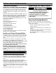
Your safety and the safety of others are very important. We have provided many important safety messages in this manual and on your appliance. Always read and obey all safety messages. This is the safety alert symbol. This symbol alerts you to potential hazards that can kill or hurt you and others. All safety messages will follow the safety alert symbol and either the word “DANGER” or “WARNING.” These words mean: You can be killed or seriously injured if you don’t immediately follow instructions.
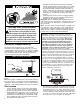
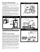
INSTALLATION INSTRUCTIONS Consumer Information Unpacking the Water Heater OBSERVE ALL GOVERNING CODES AND ORDINANCES. This water heater is design-certified by CSA International as a Category IV, direct vented water heater which takes its combustion air from the outside of the structure and exhausts all products of combustion to the outside of the structure. Excessive Weight Hazard Use two or more people to move and install water heater unless proper handling equipment is utilized.
• FIRE AND EXPLOSION HAZARD Can result in serious injury or death Do not store or use gasoline or other flammable vapors and liquids in the vicinity of this or any other appliance. Storage of or use of gasoline or other flammable vapors or liquids in the vicinity of this or any other appliance can result in serious injury or death Consider the inlet and exhaust vent system piping when selecting the water heater location.
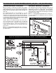
Clearances and Accessibility Notice: Minimum clearances from combustible materials are stated on the data plate located on the front of the water heater. • The water heater is certified for installation on a combustible floor. Important: If installing over carpeting, the carpeting must be protected by a metal or wood panel beneath the water heater. The protective panel must extend beyond the full width and depth of the water heater by at least 3 inches (76.
Figure 4: Condensate Drain Condensate Drain Line All parts of the condensate trap are glued except for the 1/2” CPVC drain stem joint at the elbow (see figure 3). This assembly can be turned with the outlet of the tee oriented as needed. Once orientation direction is decided, remove the unglued joint from the elbow at the bottom and apply a suitable cement to joint. Re-insert the joint fully and quickly into the elbow making sure to orient it before the cement sets.
Vent Pipe Material The following plastic materials may be used for both the combustion air inlet and exhaust outlet piping subject to state and local codes: • Schedule 40 PVC or ABS • Schedule 40 or 80 CPVC • DWV Pipe is acceptable Note: Use only solid (not foam core) piping. Plastic pipe and fittings are available through most plumbing suppliers. Always check the marking on the pipe to make sure you are using the correct material.
Vent Termination Locations The air inlet and exhaust outlet must be installed with the following minimum clearances (see figure 6): • Twelve inches above grade or maximum anticipated snow level. • Twelve inches from any opening through which flue gases could enter the structure. • Four feet horizontally and vertically from gas or electric meters, gas regulators, dryer vents, vent hoods, bathroom fan exhaust, attic fans and turbines. • Two feet from an inside corner formed by two exterior walls.
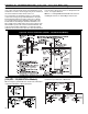
INLET/OUTLET VENT TERMINATIONS (100,000 - 150,000 BTU/HR) Standard Horizontal Termination Alternative Horizontal Termination When 3 inch pipe is used between the water heater and the outside wall, reduce it to 2 inch pipe before penetrating the wall. A maximum of 18 inches of 2 inch pipe may be used between the 3 inch transition and the inside of the wall (see figure 7A).
VERTICAL TERMINATIONS (100,000 - 150,000 BTU/HR) When 3 inch pipe is used between the water heater and the roof, reduce it to 2 inch pipe before penetrating the roof. A maximum of 18 inches of 2 inch pipe may be used between the 3 inch transition and the inside of the roof. The vertical inlet air termination requires a return bend or two short or long sweep radius 90 elbows to keep the inlet downward and prevent entry of rain.
CONCENTRIC VENT TERMINATIONS (100,000 - 150,000 BTU/HR) For new installations, install 2” Concentric vent kit model KGAVT0501CVT, part number 6910542. See Manufacturer’s instructions for complete installation or call customer service at 1-800-456-9805 for assistance. For planning purposes, see figures 10A-13A below for vent terminal specifications.
INLET/OUTLET VENT TERMINATIONS (175,000+ BTU/HR) Standard Horizontal Termination Alternative Horizontal Termination The standard horizontal air inlet termination is a 3 inch pipe which terminates at the exterior wall and utilizes a coupling to prevent the pipe from being pushed back into the structure. The standard horizontal exhaust outlet termination is a 3 inch pipe which terminates 12 inches from the outside wall.
VERTICAL TERMINATIONS (175,000+ BTU/HR) For inputs of 175,000 BTU/Hr or greater, all termination piping and fittings are 3”. Do not reduce before penetrating the wall. The vertical inlet air termination requires a return bend or two short or long sweep radius 90° elbows to keep the inlet downward and prevent entry of rain. These elbows are considered part of the termination and should not be included when calculating the maximum allowable vent pipe length.
CONCENTRIC VENT TERMINATIONS (175,000 + BTU/HR) For new installations, install 3” Concentric vent kit model KGAVT0601CVT, part number 6910543. See Manufacturer’s instructions for complete installation or call customer service at 1-800-456-9805 for assistance. Figure 13B: Concentric Vent Piping Installation For planning purposes, see figures 10B-13B below for vent terminal specifications. Figure 10B: 3 Inch Concentric Vent Figure 11B: Through the Wall Termination *100 Gallon Model Shown.
Gas Input Rate Figure 14: Input Graph The gas input rate of this water heater is affected by several environmental factors such as: • • The heating value of the gas The air and gas densities (which vary widely due to barometric pressure and temperature changes) • Venting installations (pipe diameter, length and fittings) • Altitude When measuring the input rate these factors should be incorporated into the calculations.
Figure 15: Typical One-Temperature System Piping Installation *100 Gallon Model Shown. Tempering Valve Installation Closed System/Thermal Expansion A tempering valve has been provided for use with the Polaris® Gas water heater and must be installed, per the manufacturer’s instructions, in the domestic hot water line. See Figure 16 for a sample tempering valve installation. When a backflow prevention device or check valve is installed, it can create a “Closed System.
Figure 17: Air Handler Piping Installation Massachusetts code does not allow this type of installation. *100 Gallon Model Shown. • • • • • If the space heating system requires water temperatures in excess of 120°F, a tempering valve (provided) must be installed per the manufacturer’s instructions in the potable hot water supply to limit the risk of scald injury. Pumps, valves, piping and fittings must be compatible with potable water.
Notes on Figure 18: If tank temperature is set above 120°F and water is supplied for domestic use (hand washing, showering, etc.) a tempering valve must be installed in the hot water line to domestic fixtures. Figure 18: Polaris with Auxillary Storage Tank - One or Two Temperature System (With or Without Building Recirculation) Installation must conform to local code requirements.
GAS SUPPLY AND PIPING Figure 19: Gas Piping Installation Explosion Hazard Use a new AGA or CSA approved gas supply line. Install a shut-off valve. Do not connect a natural gas water heater to a L.P. Gas Supply. Do not connect an L.P. gas water heater to a Natural Gas Supply. Failure to follow these instructions can result in death, explosion, or carbon monoxide poisoning. Gas Pressure Important: The gas supply pressure must not exceed the maximum supply pressure as stated on the water heater’s data plate.
Gas Pressure Testing Important: This water heater and its gas connection must be leak tested before placing the appliance in operation. • If the code requires the gas lines to be tested at a pressure of 14” W.C. or greater, the water heater and its manual shut-off valve must be disconnected from the gas supply piping system and the line capped. • If the gas lines are to be tested at a pressure less than 14” W.C.
ELECTRICAL CONNECTIONS Electrical Shock Hazard Disconnect power before servicing. Replace all parts and panels before operating. Failure to do so can result in death or electrical shock. If you lack the necessary skills required to properly install the electrical wiring to this water heater, do not proceed but have a qualified electrician perform the installation.
WIRING DIAGRAM TO 120/60 POWER SUPPLY FUSED DISCONNECT WHITE GND WHITE GREEN GREEN GND BLOWER BLACK BLUE RED RED NEUTRAL L1 BLOWER BLACK 120V 24V BLUE RED TRANSFORMER MODELS 130,000 BTU/Hr & Below BROWN GND IND GROUND L2 NEUTRAL (WHITE) GREEN TO 120/60 POWER SUPPLY GREEN RED THERMOSTAT SENSOR/ECO BLACK BLACK 120 VAC 120 VAC (BLACK & WHITE WIRES IN BOLD) IND L1 HSI WHITE YELLOW THERMOSTAT BOARD W PSI SEN-1 RED LOWER 24V IGNITION CONTROL PRESSURE SWITCH 120V/60Hz GR
INSTALLATION CHECKLIST Water Heater Location Requirements Centrally located with the water piping system. Located as close to the gas piping and vent pipe system as possible. Located indoors and in a vertical position. Protected from freezing temperatures. Proper clearances from combustible surfaces maintained and not installed directly on a carpeted floor. Sufficient room to service the water heater. Provisions made to protect the area from water damage.
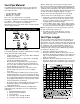
OPERATING YOUR WATER HEATER Read and understand these directions thoroughly before attempting to operate the water heater (see Operating Instructions on page 25). Check the data plate on the front of the water heater for the correct gas. Do not use this water heater with any gas other than the one listed on the data plate. If you have any questions or doubts, consult your gas supplier or gas utility company. L.P.
Stacking Stacking occurs when a series of short draws of hot water (3 gallons or less) are taken from the water heater tank. This causes increased cycling of the burner and can result in increased water temperatures at the hot water outlet. A tempering valve must be installed in the hot water supply line to reduce the risk of scald injury. Water Temperature Regulation Water temperature over 125°F can cause severe burns instantly or death from scalds.
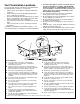
OPERATIONAL CONDITIONS Figure 23: Hand Hole Clean-out Water Heater Sounds During the normal operation of the water heater, sounds or noises may be heard. These noises are common and may result from the following: 1. Normal expansion and contraction of metal parts during periods of heat-up and cool-down. 2. Sediment buildup in the tank bottom will create varying amounts of noise and may cause premature tank failure. Drain and flush the tank as directed under “Draining and Flushing”.
MAINTENANCE OF YOUR WATER HEATER 3 Month Inspection Replacing the Gas Valve At least every 3 months, a visual inspection should be made of the combustion air inlet as well as the exhaust and water piping. Check the water heater for the following: • Obstructions, damage, or deterioration in the venting system. Make sure the exhaust and combustion air supplies are not obstructed. • Leaking or damaged water and gas piping. • Presence of flammable or corrosive materials in the installation area.
TROUBLESHOOTING Ignition Control Module (ICM) LED Error Codes: (Flashes visible through viewport in access door) FLASHES 1 2 3 4 5 6 8 9 Rapid INDICATED PROBLEM Pressure Switch Closed Pressure Switch Open Failed Ignition Gas Valve Hardware Fault Flame Sense Hardware Fault False Flame Ignition Control Hardware Fault Ignition Control Software Fault L1 Polarity Detection CONTROL REACTION SC* SL SL3 SL SC SL** SL SL SC SL (Soft Lockout): Control Automatically resets after 60 minutes.
SOFTWARE OPERATION SEQUENCE IGNITION CONTROL MODULE SOFTWARE OPERATION SEQUENCE * For 175,000 BTU/Hr models and above the flame establishing period is six seconds. For the first 3 seconds the gas valve is off.
REPAIR PARTS LIST/DIAGRAM 31B 1 1 33 1 ALL MODELS EXCEPT 100 GALLON When ordering repair parts always give the following information: 1. Model, serial, and product numbers 2. Type of gas 3. Item number 4. Parts description 2 3 4 5 8 6 17 16 12 7 15 22 23 20 21 24 Repair Parts List 30 ITEM NO.
REPAIR PARTS LIST/DIAGRAM 1 4 5 35 2 6 100 GALLON MODELS When ordering repair parts always give the following information: 1. Model, serial, and product numbers 2. Type of gas 3. Item number 4. Parts description 7 9 8 10 3 14 11 12 1 19 13 15 17 34 20 16 Repair Parts List ITEM NO.
POLARIS MODELS & DIMENSIONS 34/50 Gallon Units 100 Gallon Units Clean-out Port MODEL NUMBER 32 GAL. CAP. INPUT (MBTU PER HR.) VENT DIA. T&P HGT GAS SUPPLY AIR INLET/ EXHAUST B C D E F G APPROX SHIP.