Operating Manual CCD Camera Models ST-7E, ST-8E, ST-9E, ST-10E and ST-1001E Santa Barbara Instrument Group 147A Castilian Drive Santa Barbara, CA 93117 Phone (805) 571-7244 • Fax (805) 571-1147 Web: • Email:
Note: This equipment has been tested and found to comply with the limits for a Class B digital device pursuant to Part 15 of the FCC Rules. These limits are designed to provide reasonable protection against harmful interference in a residential installation. This equipment generates, uses, and can radiate radio frequency energy and if not installed and used in accordance with the instructions, may cause harmful interference to radio communications.
Table of Contents 1. 1.1. 1.2. Introduction .................................................................................................................1 Road Map of the Documentation ...............................................................................1 Quick Tour....................................................................................................................1 1.2.1. CCDOPS Software ....................................................................................2 1.2.
.6 Connecting the older model CFW-6 filter wheel to the Camera ..................................30 4.7 Battery Operation .............................................................................................................31 4.8 ST-1001E Differences ........................................................................................................31 5. 5.1. 5.2. 5.3. 5.4. 5.5. 5.6. 5.7. 5.8. Advanced Imaging Techniques .........................................................................
Section 1 - Introduction 1. Introduction Congratulations and thank you for buying one of Santa Barbara Instrument Group's CCD cameras. The model ST-7E, ST-8E, ST-9E, ST-10E and ST-1001E are SBIG's fourth generation CCD cameras and represent the state of the art in CCD camera systems with their low noise and advanced capabilities, including Kodak's new Blue Enhanced E series of CCDs.
Section 1 - Introduction 1.2.1. CCDOPS Software Follow the instructions below to run the CCDOPS software and display and process sample images included on the distribution diskette. • Install the software onto your hard disk. For Windows this involves running the Setup.exe file on the first diskette. For Macintosh or DOS this involves copying the contents of the floppy disk to a folder or directory on your hard disk.
Section 1 - Introduction • Load up the other sample images and display them using the photo display mode. • If you find that the display is too dark or bright, try setting Auto Contrast in the display menu or adjust the background and range parameters to achieve the best display. Usually your monitor brightness and contrast want to be set fairly high. Note: Full daylight at F/22 will saturate these cameras with the shortest exposure. With a camera lens start out in dim room light.
Section 2 - Introduction to CCD Cameras 2. Introduction to CCD Cameras This section introduces new users to CCD (Charge Coupled Device) cameras and their capabilities and to the field of CCD Astronomy and Electronic Imaging. 2.1. Cameras in General The CCD is very good at the most difficult astronomical imaging problem: imaging small, faint objects. For such scenes long film exposures are typically required.
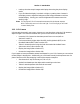
Section 2 - Introduction to CCD Cameras transports the charge packets in a serial manner to an on-chip amplifier. The final operating step, charge detection, is when individual charge packets are converted to an output voltage. The voltage for each pixel can be amplified offchip and digitally encoded and stored in a computer to be reconstructed and displayed on a television monitor."1 Output Readout Register Y=1 Amplifier Y=N X=1 X=M Figure 2.1 - CCD Structure 2.2.1.
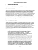
Section 2 - Introduction to CCD Cameras TE Cooler Microcontroller Clock Drivers 16 Bit A/D Preamp PC Interface Telescope Interface Desktop Power Supply Tracking CCD Shutter Imaging CCD Host Computer Parallel Interface Figure 2.2 - CCD System Block Diagram As you can see from Figure 2.2, the ST-7E, ST-8E, ST-9E, ST-10E and ST-1001E are completely self contained. Unlike our previous products, the ST-7E, ST-8E, ST-9E, ST-10E and ST-1001E contain all the electronics in the optical head.
Section 2 - Introduction to CCD Cameras The CCD is cooled with a solid-state a thermoelectric (TE) cooler. The TE cooler pumps heat out of the CCD and dissipates it into a heat sink which forms part of the optical head's mechanical housing. In the ST-7E and ST-8E cameras this waste heat is dumped into the air using passive radiators and a small fan, making the design and operation of the heads simple and not inconvenienced by requirements for liquid recirculation cooling.
Section 2 - Introduction to CCD Cameras current, which can cause each pixel to fill with electrons in only a few seconds at room temperature even in the absence of light. By cooling the CCD, the dark current and corresponding noise is reduced, and longer exposures are possible. In fact, for roughly every 5 to 6° C of additional cooling, the dark current in the CCD is reduced to half.
Section 2 - Introduction to CCD Cameras at the same temperature and for the same duration as the light frame with the source of light to the CCD blocked so that you get a "picture" of the dark. This dark frame will contain an image of the noise caused by dark current (thermal noise) and other fixed pattern noise such as read out noise. When the dark frame is subtracted from the light frame, this pattern noise is removed from the resulting image.
Section 2 - Introduction to CCD Cameras people think that smaller pixels are a plus, you pay the price in sensitivity due to the fact that smaller pixels capture less light. For example, the ST-9E with its large 20 x 20 micron pixels captures five times as much light as the ST-7E and ST-8E's 9 micron square pixels. For this reason we provide 2x2 or 3x3 binning of pixels on most SBIG cameras. With the ST-7 and ST-8, for instance, the cameras may be configured for 18 or 27-micron square pixels.
Section 2 - Introduction to CCD Cameras Track and Accumulate to co-add several shorter images. The dual CCD design allows the guiding CCD access to the large aperture of the main telescope without the inconvenience of off-axis radial guiders. Not only are guide stars easily found, but the problems of differential deflection between guide scope and main scope eliminated. Due to the large size of the imaging CCD in the ST-1001E, however, a second CCD for tracking cannot be used.
Section 2 - Introduction to CCD Cameras Of course, once the image is stored on a computer disk, it may be transferred to another computer just like any other data file. You can copy it or send it via modem to a friend, upload it to your favorite bulletin board or online service, or store it away for processing and analysis at some later date. We have found that an easy way to obtain a hard copy of your electronic image is to photograph it directly from the computer screen.
Section 3 - At the Telescope with a CCD Camera 3. At the Telescope with a CCD Camera This section describes what goes on the first time you take your CCD camera out to the telescope. You should read this section throughout before working at the telescope. It will help familiarize you with the overall procedure that is followed without drowning you in the details. It is recommended you first try operating the camera in comfortable, well lit surroundings to learn its operation. 3.1.
Section 3 - At the Telescope with a CCD Camera RA DEC * Figure 3.1 Orientation of the Optical Head Viewed from Back. (Pixel 1,1 is at the upper left in this view) 3.3. Establishing a Communications Link When the CCDOPS program is initiated it will automatically attempt to establish a link to the camera. This involves identifying the type of CCD head. If the software is successful the "Link" field in the Status Window is updated to show the type of camera found.
Section 3 - At the Telescope with a CCD Camera This preliminary step will save you much time in initially finding focus. The approximate distance behind the eyepiece tube for each of our CCD cameras is listed in Table 3.1 below: Camera ST-5C ST-237/A/STV ST-6 ST-7E/8E/9E/ST-10E ST-1001E Distance ~0.66 inch ~0.68 inch ~0.56 inch ~0.92 inch ~0.68 inch Diffuser Back Focus Distance from Table 3.1 Table 3.
Section 3 - At the Telescope with a CCD Camera eyepiece and slide it back and forth to find the best visual focus, and then scribe the outside of the eyepiece barrel. The next time the CCD is used the eyepiece should be first inserted into the tube to the scribe mark, and the telescope visually focused and centered on the object. At f/6 the depth of focus is only 0.005 inch, so focus is critical. An adapter may be necessary to allow the eyepiece to be held at the proper focus position.
Section 3 - At the Telescope with a CCD Camera 3.8. Processing the Image If not done already, images can be improved by subtracting off a dark frame of equal exposure. You will typically do this as part of the Grab command although it can also be done manually using the Dark Subtract command. By subtracting the dark frame, pixels which have higher dark current than the average, i.e., "hot" pixels, are greatly suppressed and the displayed image appears much smoother.
Section 3 - At the Telescope with a CCD Camera Another aspect of the Focus command and its various modes is the Camera Resolution4 setting in the Camera Setup command. Briefly, the Resolution setting allows trading off image resolution (pixel size) and image capture time while field of view is preserved. High resolution with smaller pixels takes longer to digitize and download than Low resolution with larger pixels. The cameras support High, Medium, Low and Auto resolution modes.
Section 3 - At the Telescope with a CCD Camera One of the reasons that SBIG autoguiders are often better than human guiders is that, rather than just stabbing the hand controller to bump the guide star back to the reticule, it gives a precise correction that is the duration necessary to move the guide star right back to its intended position. It knows how much correction is necessary for a given guiding error through the Calibrate Track command.
Section 3 - At the Telescope with a CCD Camera Color imaging places some interesting requirements on the user that bear mentioning. First, many color filters have strong leaks in the infrared (IR) region of the spectrum, a region where CCDs have relatively good response. If the IR light is not filtered out then combining the three images into a color image can give erroneous results. If your Blue filter has a strong IR leak (quite common) then your color images will look Blue.
Section 4 - Camera Hardware 4. Camera Hardware This section describes the modular components that make up the CCD Camera System and how they fit into the observatory, with all their connections to power and other equipment. 4.1. System Components The ST-7E, ST-8E, ST-9E, ST-10E and ST-1001E CCD cameras consist of four major components: the CCD Sensors and Preamplifier, the Readout/Clocking Electronics, the Microcontroller, and the power supply.
Section 4 - Camera Hardware Typically you would take ten 1 minute "snapshots" to produce an image that is comparable to a single 10 minute exposure except that no guiding is required. The reason no guiding is required is that with most modern telescope mounts the drift over the relatively short 1 minute interval is small enough to preserve round star images, a feat that even the best telescope mounts will not maintain over the longer ten minute interval.
Section 4 - Camera Hardware In our older camera models and in the optional relay adapter accessory, each of the relays has a Common, a Normally Open, and a Normally Closed contact. For example, when the relay is inactivated there is a connection between the Common and the Normally Closed contact. When the relay is activated (trying to correct the telescope) the contact is between the Common and the Normally Open contacts.
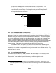
Section 4 - Camera Hardware used to attach to the wiper to either end of the potentiometer when the opposing relays are activated. A + relay wiper - relay c A B nc C c B potentiometer nc no no C B: Modified Joystick A: Unmodified Joystick Figure 4.3 - Joystick Modification A slight variation on the joystick modification is to build a complete joystick eliminator as shown in Figure 4.4 below.
Section 4 - Camera Hardware software. Software developers can produce one package for the many users across the model line instead of different packages for each of the cameras. While the SBIG cameras have many similarities, there are also important differences between the products. Table 4.
Section 4 - Camera Hardware CCD Used Number of Pixel Array Camera Pixels Dims. Dimension Tracking TC-211 192 x 164 13.75 x 16 µ 2.6 x 2.6mm CCD ST-5C TC-255 320 x 240 10 x 10 µ 3.2 x 2.4mm ST-237A TC-237 657 x 495 7.4 x 7.4 µ 4.7 x 3.6mm STV TC-237 320 x 200 14.8 x 14.8 µ 4.7 x 3.0mm ST-6 TC-241 375 x 242 23 x 27 µ 8.8 x 6.6mm ST-7E KAF0401E 765 x 510 9x9µ 6.9 x 4.6mm ST-8E KAF1602E 1530 x 1020 9 x 9 µ 13.8 x 9.2mm ST-9E KAF0261E 512 x 512 20 x 20 µ 10.2 x 10.2mm ST-10E KAF3200E 2184 x 1472 6.8 x 6.8 µ 14.
Section 4 - Camera Hardware length is the focal length of the telescope or lens. Also remember that 1° = 3600 arcseconds. Read Noise - The readout noise of a CCD camera affects the graininess of short exposure images. For example, a CCD camera with a readout noise of 30 electrons will give images of objects producing 100 photoelectrons (very dim!) with a Signal to Noise (S/N) of approximately 3 whereas a perfect camera with no readout noise would give a Signal to Noise of 10.
Section 4 - Camera Hardware C8, 8" f/10 LX200, 10" f/36 Field of Pixel Field of Pixel View Size View Size Camera (arcmins) (arcsecs) (arcmins) (arcsecs) Tracking 4.2x4.2 1.3x1.5 11.7x11.7 3.7x4.3 CCD ST-5C 5.4x4.1 1.0x1.0 14.4x10.8 2.7x2.7 ST-237 8.0x6.0 0.75x0.75 21.6x16.2 2.0x2.0 STV 8.0x5.0 1.5x1.5 21.6x13.5 4.0x4.0 ST-6 14.6x11.1 2.3x2.7 38.9x29.5 6.2x7.3 ST-7E 11.9x7.9 0.9x0.9 31.2x20.8 2.4x2.4 ST-8E 23.8x15.8 0.9x0.9 62.4x41.6 2.4x2.4 ST-9E 17.6x17.6 2.0x2.0 46.2x46.2 5.3x5.3 ST-10E 25.1x16.9 0.7x0.
Section 4 - Camera Hardware ST-7E/8E/9E/10E head. The phone cable connection connects to the telescope drive to adjust the telescope position when collecting images using Self-Guiding, and the short cable with three wires connects to the CFW-6. The black wire of the three-wire group mates to the brown or black wire of the CFW-6. 4.7 Battery Operation The ST-7E/8E/9E/10E can be operated off of a 12 volt car or marine battery using a the optional 12V power supply or using a power inverter.
Section 5 - Advanced Imaging Techniques 5. Advanced Imaging Techniques With practice, you will certainly develop methods of your own to get the most from your CCD camera. In this section we offer some suggestions to save you time getting started in each of the different areas outlined below, but these suggestions are by no means exhaustive. 5.1.
Section 5 - Advanced Imaging Techniques the twilight sky near the horizon or take an image of a blank wall or neutral grey card. The Kodak CCDs may have a low contrast grid pattern visible in the sky background. A flat field will eliminate this. Finding areas of the sky devoid of stars is very difficult after twilight. Therefore, you should take flat field images of the night sky after sunset, but long before you can see any stars.
Section 5 - Advanced Imaging Techniques is best for critical focusing. Planet mode will result in fast digitization and download times since only a small portion of the frame is read out. In general, you should pick a binning mode that yields stars with two to three pixels full width at half maximum. This is easily measured by using the crosshairs to determine the peak brightness of a relatively bright star, and determining the number of pixels between the 50% values on either side of the peak.
Section 5 - Advanced Imaging Techniques 5. Repeat steps 3 and 4 as many times as desired for all the objects you wish to image, each time choosing a set of corresponding new names for the IMAGE and TRACK files. 6. You will now create a combined flat field image for each Track and Accumulate image you captured. Invoke the Add by Track List command. The software will bring up a file directory dialog showing all the track list files. Select the TRACK file corresponding to the image you wish to correct.
Section 5 - Advanced Imaging Techniques absolutely necessary. Finally, modern drive correctors with periodic error correction (PEC) or permanent periodic error correction (PPEC) will ease the difficulty of achieving good results. The moral of the story is don't count on the CCD autoguider to fix all your problems. The better the drive, the better results you will obtain. Using the CCD as an autoguider requires interfacing the CPU's relay port to your hand controller (as discussed in section 4.
Section 6 - Accessories for your CCD Camera 6. Accessories for your CCD Camera This section briefly describes the different accessories available for your CCD camera. 6.1. Cooling Booster The cooling booster, which is included with the ST-9E and ST-10E, is an option for the ST-7E, ST-8E and ST-1001E. It is a small module that gets installed inside the back compartment of the camera. This section tells you how to best use the Cooling Booster.
Section 6 - Accessories for your CCD Camera reservoir from a significant height above it, such a 0.3 meter (12 inches). Lastly, check for leaks! When using water cooling, avoid the temptation to put ice in the water to get the camera even colder. As the cooling booster is designed, the camera will not be cooled below ambient temperature if ambient temperature water is used. If colder water is used, the head may fog or frost up, depending on the dew point. .
Section 6 - Accessories for your CCD Camera 6.5. AO-7 and Lucy-Richardson Software The AO-7 is the world's only Adaptive Optics accessory for the amateur CCD market and it works only with the self guided feature of the ST-7E/8E/9E/10E. The AO-7 is essentially an electromechanical driven diagonal mirror that goes between the camera and the telescope. Using the AO-7 allows corrections to be made at rates up to 40 Hz. This yields perfect, backlash-free guiding and allows removal of some atmospheric effects.
Section 6 - Accessories for your CCD Camera the screen, and use an exposure longer than 1/30th of a second to avoid the video refresh rate of your monitor. Darken the room, and use a brighter background than is visually optimum. For the best quality hard copy, save the files in TIFF format and send a copy of the file on a disk to a photo lab which offers printing of digital images.
Section 8 - Glossary 7. Common Problems This section discusses some of the more common problems others have encountered while using our CCD cameras. You should check here if you experience difficulties, and if your problem still persists please contact us to see if we can work it out together. Achieving Good Focus - Achieving a good focus is one of the most difficult areas in working with CCD cameras due to the lack of real time feedback when focusing.
Section 8 - Glossary The easiest method of finding objects is to use a reticule eyepiece, if the object is bright enough to see. Pull the CCD optical head from the eyepiece holder and insert a 12-20mm eyepiece, focussing the eyepiece by sliding it in and out of the eyepiece holder, not by adjusting the telescope's focus mechanism. Center the object carefully (to within 10% of the total field) and then replace the CCD optical head.
Section 8 - Glossary 8. Glossary Antiblooming Gate - When a CCD pixel has reached its full well capacity, electrons can effectively spill over into an adjoining pixel. This is referred to as blooming. Kodak CCDs with the antiblooming option can be used to help stop or at least reduce blooming when the brighter parts of the image saturate. Astrometry - Astrometry is the study of stellar positions with respect to a given coordinate system.
Section 8 - Glossary Flat Field - A Flat Field is a image with a uniform distribution of light entering the telescope. An image taken this way is called a flat field image and is used with CCDOPS to correct images for vignetting. Focal Reducer - A Focal Reducer reduces the effective focal length of an optical system. It consists of a lens mounted in a cell and is usually placed in front of an eyepiece or camera.
Section 8 - Glossary Planet Mode - Planet Mode is the most useful way to achieve focus. When you select Planet mode, a full frame is exposed, downloaded, and displayed on the computer monitor. A small window can be placed anywhere in the image area and the size of the window can be changed. Subsequent downloads will be of the area inside the box resulting in a much faster update rate.
Section 8 - Glossary Sky Background - The sky background illumination or brightness is the number of counts in the image in areas free of stars or nebulosity and is due to city lights and sky glow. High levels of sky background can increase the noise in images just like dark current. For some objects deep sky filters can be used to reduce the sky background level. Seeing - Seeing refers to the steadiness and the clarity of the atmosphere during an observing session.
Appendix A - Connector Pinouts A. Appendix A - Connector ad Cables This appendix describes the various connectors and cables used with the ST7E/8E/9E/10E/1001E. A.1. Appendix A - Connector Pinouts Tables A1 and A2 below show the pin-outs of the Telescope and Power connectors on the ST7E/8E/9E.
Appendix A - Connector Pinouts the Celestron Ultima, Losmandy CG11 and Meade LX-200. You can interface these telescopes to the Telescope port with our TIC-78 (Tracking Interface Cable), or you can make your own cable. Figure A1 below shows the pinouts on these telescopes.
Appendix B - File Formats B. Appendix C - Maintenance This appendix describes the maintenance items you should know about with your CCD camera system. B.1. Cleaning the CCD and the Window The design of SBIG cameras allows for cleaning of the CCD. The optical heads are not evacuated and are quite easy to open and clean. When opening the CCD chamber, one should be very careful not to damage the structures contained inside.
Appendix C - Capturing a Good Flat Field C. Appendix C - Capturing a Good Flat Field This appendix describes how to take a good flat field. A good flat field is essential for displaying features little brighter than the sky background. The flat field corrects for pixel non-uniformity, vignetting, dust spots (affectionately called dust doughnuts), and stray light variations. If the flat field is not good it usually shows up as a variation in sky brightness from on side of the frame to the other. C.1.
Index A/D converter, 8, 27 accessories, 41 adaptive optics, 40 antiblooming, 29, 45 Antiblooming Gate (def), 45 AO-7, 40 astrometric measurements, 45 Astrometry (def), 45 astrophotography, 12 atmospheric effects, 17 auto contrast, 18 Auto Grab Command, 21 autoguider, 8, 20, 23, 36, 45 Autoguider (def), 45 background parameter, 18 battery operation, 15, 23 binning, 10 Calibrate Track Command, 21, 37 calibration star, 37 camera lens adapter, 33, 40 Camera Setup Commands, 20 CCD, 7, 11 (def), 45 cameras, 5, 6,
Index focal reducer, 40 Focal Reducer (def), 46 focus Dim mode, 18, 19 fine, 17 Full frame mode, 17 Full Frame mode, 19 peak, 17 Planet mode, 17, 19, 46 Focus Command, 17, 19 focus mode, 17, 19 Focusing, 16 Frame Transfer CCDs, 6 Frame Transfer CCDs (def), 46 frost, 8 Full Frame CCDs, 6 full well capacity, 29 Full Well Capacity (def), 46 Grab Command, 18, 33 graphics, 18 guiding, 11 guiding error, 20, 37 hand controller, 18, 20, 23, 24 hermetic chamber, 8 Histogram (def), 46 host computer, 8, 15, 23 hot pix
Index shutter, 8 signal to noise ratio, 22, 29 sky background, 5, 20 smoothing, 19 snapshot, 23 software, 26, 41 spectral range, 5 spectrograph, 41 Status Window, 16 Link field, 16 stellar magnitude, 19 stellar temperature, 19 super pixel, 19 taking images, 18 TE cooler, 8 TE Cooler, 7 TE Cooler (def), 48 Technical Support, 42 telescope, 10, 15, 18, 20 Telescope connector, 49 telescope hand controller, 18, 20, 23, 24 temperature regulation, 9, 18, 27 thermistor, 9 TIC, 49 TIC-78, 24 TIFF format (def), 48 Tr