
Operating Manual CCD Camera Models ST-7E, ST-8E, ST-9E, ST-10E, ST-1001E

Section 4 - Camera Hardware
Page 26
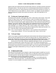
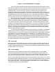
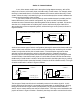
used to attach to the wiper to either end of the potentiometer when the opposing relays are
activated.
potentiometer
A
B
C
A: Unmodified Joystick
wiper
B: Modified Joystick
nc
c
no
+ relay
A
B C
nc
c
no
- relay
Figure 4.3 - Joystick Modification
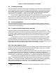
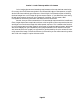
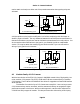
A slight variation on the joystick modification is to build a complete joystick eliminator as
shown in Figure 4.4 below. The only difference between this and the previous modification is
that two fixed resistors per axis are used to simulate the potentiometer at its mid position. You
do not need to make modifications to the joystick; you essentially build an unadjustable
version. This may be easier than modifying your hand controller if you can trace out the
wiring of your joystick to its connector.
potentiometer
A
B
C
A: Unmodified Joystick
R
wiper
B: Joystick Eliminator
nc
c
no
+ relay
B C
A
nc
c
no
- relay
R/2 R/2
Figure 4.4- Joystick Eliminator
4.5. Modular Family of CCD Cameras
With the introduction of the ST-6 CCD Camera in 1992 SBIG started a line of high quality, low
noise, modular CCD cameras. The ST-7E, ST-8E and ST-9E were a second family of modular
CCD cameras. The ST-10E and ST-1001E will also allow for upgrades to a faster USB interface
when available.
The benefits of a modular line of CCD Cameras are manyfold. Users can buy as much
CCD Camera as they need or can afford, with the assurance that they can upgrade to higher
performance systems in the future. With a modular approach, camera control software like
CCDOPS can easily support all models. This last point assures a wide variety of third party