
Operating Manual CCD Camera Models ST-7E, ST-8E, ST-9E, ST-10E, ST-1001E


Appendix A - Connector Pinouts
Page 49
A. Appendix A - Connector ad Cables
This appendix describes the various connectors and cables used with the ST-
7E/8E/9E/10E/1001E.
A.1. Appendix A - Connector Pinouts
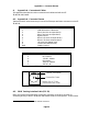
Tables A1 and A2 below show the pin-outs of the Telescope and Power connectors on the ST-
7E/8E/9E.
Pin Number Function
1 Chassis Ground
2 CFW-8 Pulse/AO-7 Data Out
3 Plus X (Active Low Open Drain)
9
4 Plus Y (Active Low Open Drain)
5 Signal Ground
6 Minus X (Active Low Open Drain)
7 Minus Y (Active LowOpen Drain)
8 +12 Volts Out (100mA max)
9 +5 Volts Out (300 mA max)
Shell Chassis Ground
Table A1 Telescope Connector
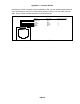
Pin Number Function
6, Shell Earth Ground
5 DC Ground
4 -12V DC, 100mA
3 No contact
2 +12V DC, 500mA
1 +5V DC, 2A
Table A2 Power Connector
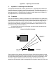
Ground in Center
+12VDC on outside
Mating plug is 5.5mm
outside and 2.1mm inside
Figure A1 - Cooling Booster DC Power Jack
A.2. SBIG Tracking Interface Cable (TIC-78)
Many of the newer telescopes have a phone-jack connector on the drive corrector for
connecting directly to the ST-7E/8E/9E/10E/1001E Camera's Telescope Port. These include
9
The Open Drain outputs can sink 100 mA maximum