2006 LCD Models – North America FLM-4034B, FLM-4232HM, FLM-4234BH SERVICE MANUAL Bezel covers vary by model 20070415
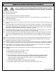
Important Service and Safety Information Prior to using this service manual, please ensure that you have carefully followed all the procedures outlined in the user's manual for this product. (1) Read all of these instructions. (2) Save these instructions. (3) Follow all warnings and instructions marked on the product. (4) Unplug this product from the wall outlet before cleaning. Do not use liquid cleaners or aerosol cleaners; use a damp cloth for cleaning. (5) Do not use this product near water.
Important Service and Safety Information Service work should be performed only by qualified service technicians familiar with all safety checks and these service guidelines: ELECTRIC SHOCK HAZARD Always disconnect AC power before servicing! Never modify any circuit! Never insert any objects into the holes in the TV case! ELECTROSTATIC DISCHARGE (ESD) Components inside an LCD or plasma TV are sensitive to static electricity.
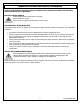
Important Service and Safety Information PRECAUTIONS FOR USING LEAD-FREE SOLDER Components within this television use lead-free solder (Sn-Ag-Cu). Whenever soldering, look at the markings on boards and components within the television to determine the correct solder type according to the table below.
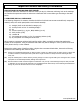
Table of Contents 1. 2. 3. 4. 5. 6. 7. 8. 9. 10. Operation ......................................................................................................................................... 6 Troubleshooting / Flow Charts ......................................................................................................... 14 Polaroid Display Cell Defect Specification ..........................................................................................
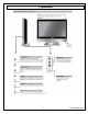
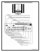
1. Operation 6 www.polaroid.
www.polaroid.
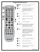
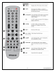
Original Remote Control 8 www.polaroid.
www.polaroid.
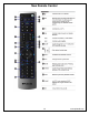
New Remote Control 10 www.polaroid.
www.polaroid.
The operation of each OSD control is described in the following table: Menu Options Sub-Options Function and Description VIDEO Picture Mode Vivid →Hi-Bright →Cinema →Sport→User. Press repeatedly for different picture modes: Vivid →Hi-Bright →Cinema→Sport →User.
Closed Caption C1,C2,C3,C4,T1,T2, TT4,and Off Set the closed caption mode. V-chip Input Password Block MPAA Rating Input the 4-digit password. “0000” Set the input source that you want to lock. Input the old password first, and then input the new password. Block all unrated movies. Block all unrated TV programs. Reset the items in the setup menu except the protected items. To set the audio language to English, French, or Spanish.
2. Troubleshooting / Flow Charts Note: Reseat all cables, check fuse by AC plug, perform a clear or reset in factory mode and retest before ordering parts. Can’t power on your TV? This TV is equipped with a safety fuse. In the event of an electrical storm or power outage the safety fuse is designed to protect your TV. If your TV has no power, check the fuse by prying the cover off, following the illustration below.
www.polaroid.
www.polaroid.
www.polaroid.
3. Polaroid Display Cell Defect Specification In some cases, a panel may have defective cells that cannot be controlled.
4. Before Returning This Product to the User Before returning this product to the user, always perform the following safety checks: (4) Inspect all wiring to be sure no wires are pinched between the chassis or any metal parts. (5) Inspect all protective devices for proper installation, including non-metallic controls, insulation materials, cabinet backs, compartment covers, and shields.
5. Disassembly Procedure Note: Before disassembly of any part the TV, make sure the power is OFF, and the power cord is removed from the wall outlet. Allow time for power within all system boards to discharge before you begin disassembly. Never insert any objects into the vent holes in the TV case. Note: Before returning this product to the end user, you must follow the steps outlined in the section, Before Returning This Product to the User, on page 19.
Stand and Control Box Removal – All Models Lay TV flat on workbench. Be careful to protect the front bezel and LCD screen from being scratched. Use protective cloth between work bench and TV front. Note: Before disassembly of any part the TV, make sure the power is OFF, and the power cord is removed from the wall outlet. Allow time for power within all system boards to discharge before you begin disassembly. Never insert any objects into the vent holes in the TV case.
(3) Remove 2 screws (A) from the Control Box. A (4) Lift the Control Box upwards, and then towards to bottom of the TV to unhook it. (5) Unplug the 2 cables (A) from the Control Box, and remove the Box from the TV. A Note: Before returning this product to the end user, you must follow the steps outlined in the section, Before Returning This Product to the User, on page 19. This procedure ensures that the chassis will not cause electric shock. 22 www.polaroid.
Rear Cabinet Cover, LCD Panel and Front Bezel – FLM-4034B Note: Before disassembly of any part the TV, make sure the power is OFF, and the power cord is removed from the wall outlet. Allow time for power within all system boards to discharge before you begin disassembly. Never insert any objects into the vent holes in the TV case. Note: OEM LCD panels were used in production. The following LCD panel disassembly/removal instructions may not apply to all models.
(3) Remove 4 EMI Foam Standoffs (A) and EMI Aluminum Foil Shielding Tape (B). B A NOTE: (4) You MUST re-install the EMI Foam Standoffs and EMI Aluminum Foil Shielding Tape when reassembling the TV. From the D-sub board, remove the Speaker wires, Front/Side Control Button wire, LCD Panel wire, and A/V wire. Speaker Wire Front/Side Control Button A/V Wire D-sub board LCD Panel Wire Black Tape (5) Remove the black tape from the Speaker wire and Ceramic ring (PIC2) and SAVE for reassembly.
(6) Remove 8 screws (A) and remove the stand support frame from the TV. A (7) Remove 4 screws (A) from the left side frame support. A (8) Remove 4 screws (A) from the right side frame support. A 25 www.polaroid.
(9) Remove 4 screws (A) from the bottom of the left and right side frame supports, and remove the frame supports from the TV. A (10) Remove 6 screws (A) from the LCD Panel, and remove it from the TV. A NOTE: To avoid damage, TWO PEOPLE ARE REQUIRED to lift the LCD Panel from the TV. Note: Before returning this product to the end user, you must follow the steps outlined in the section, Before Returning This Product to the User, on page 19.
Rear Cabinet Cover, LCD Panel and Front Bezel – FLM-4232HM, FLM4234BH Note: Before disassembly of any part the TV, make sure the power is OFF, and the power cord is removed from the wall outlet. Allow time for power within all system boards to discharge before you begin disassembly. Never insert any objects into the vent holes in the TV case. Note: OEM LCD panels were used in production. The following LCD panel disassembly/removal instructions may not apply to all models.
(3) Remove 4 EMI Foam Standoffs (A) and EMI Aluminum Foil Shielding Tape (B). B A NOTE: (4) You MUST re-install the EMI Foam Standoffs and EMI Aluminum Foil Shielding Tape when reassembling the TV. From the D-sub board, remove the Speaker wires, Front/Side Control Button wire, LCD Panel wire, and A/V wire. Speaker Wire Front/Side Control Button A/V Wire D-sub board LCD Panel Wire Black Tape (5) Remove the black tape from the Speaker wire and Ceramic ring (PIC2) and SAVE for reassembly.
(6) Remove 12 screws (A) and remove the stand support frame from the TV. A (7) Remove 6 screws (A) from the left side frame support. A (8) Remove 6 screws (A) from the right side frame support. A 29 www.polaroid.
(9) Remove 6 screws (A) from the left side frame support. A Close-up of screws in frame support (2 screws in each slot). (10) Remove 6 screws (A) from the right side frame support. Close-up of screws in frame support (2 screws in each slot). A (11) Remove 2 screws (A) from the left and right frame supports (4 total), and remove both frame supports from the TV. A 30 www.polaroid.
(12) Remove 18 screws (A) from the LCD Panel, and remove it from the TV. A NOTE: To avoid damage, TWO PEOPLE ARE REQUIRED to lift the LCD Panel from the TV. Note: Before returning this product to the end user, you must follow the steps outlined in the section, Before Returning This Product to the User, on page 19. This procedure ensures that the chassis will not cause electric shock. 31 www.polaroid.
A/V Board Removal and Replacement Note: Before disassembly of any part the TV, make sure the power is OFF, and the power cord is removed from the wall outlet. Allow time for power within all system boards to discharge before you begin disassembly. Never insert any objects into the vent holes in the TV case. (1) Disassemble control box cover and rear cabinet cover and remove A/V assembly.
IR Board Removal and Replacement Note: Before disassembly of any part the TV, make sure the power is OFF, and the power cord is removed from the wall outlet. Allow time for power within all system boards to discharge before you begin disassembly. Never insert any objects into the vent holes in the TV case. (1) Disassemble rear control box cover and rear cabinet cover. (2) 2. Remove screws 1 and 2 and replace IR board (PIC1).
Front/Side Control Buttons Removal and Replacement Note: Before disassembly of any part the TV, make sure the power is OFF, and the power cord is removed from the wall outlet. Allow time for power within all system boards to discharge before you begin disassembly. Never insert any objects into the vent holes in the TV case. (1) Disassemble control box cover and rear cabinet cover. (2) The control button board is attached with glue.
6. Spare Parts Lists Attention Service Centers Some models consist of parts with multiple versions. Replacement parts in the spare part lists with an asterisk (*) are multiple version parts. The TV serial number Model Version is used to identify the replacement part(s) needed for repair. Below is the Polaroid serial number format breakdown with a sample serial number. Reference the serial number format details below to identify the correct replacement part(s) before placing replacement part orders.
Polaroid FLM-4034B Part Number 600-181-3200-LIH 621-181-60002H 621-181-2000H 621-181-3020P-1H 845-C45-GF1XA-PH 909-KS0-GF401XA2H 899-K00-GF271XAH 154-501-GF370-AH 899-E00-GF271XAH 899-A00-GF271XAH 705-540-011SH 151-A01-FU68B7WH 151-001-FU67GH 154-004-GF32WH 151-700-GF401XABH 824-015-GF321L-KH 631-030-JK401XAH Description AC Power Cord Audio Cable Composite Video Cable Component Cable Remote Control Control Box Assembly (Samsung) Front/Side Control Button Bd.
Polaroid FLM-4234BH Model Version* 01 02 01 02 01 02 01 02 Part Number 600-181-3200-LIH 621-181-60002H 621-181-2000H 621-181-3020P-1H 845-C45-GF1XA-PH 909-KJ0-GF421UA2H 909-KL0-GF4211UA2H 899-K00-GF271XAH 154-500-GF321H 899-E00-GF271XAH 899-A00-GF271XAH 705-542-001CH 705-542-004LH 151-A01-FV18B7WCH 151-A01GF428B7WL0H 151-001-FV17GH 154-004-GF32WH 151-700-GF421UABH 824-020-A002H 631-030-GF421XA-CH 631-030-GF421UA-LH 631-024-GF371-CH Description AC Power Cord Audio Cable Composite Video Cable Component C
7. Exploded View Diagram FLM-4034B FLM-4232HM, FLM-4234BH 38 www.polaroid.
8. Block Diagram 39 www.polaroid.
www.polaroid.
9. Schematics Power & LDO 41 www.polaroid.
VGA In / LVDS & Back Light 42 www.polaroid.
Audio ADC/DAC & OP 43 www.polaroid.
GPIO & Placement 44 www.polaroid.
Power 45 www.polaroid.
Tuner 46 www.polaroid.
HMDI connector is a type A receptacle for video/audio mode. 1. TMDS 2. TMDS 3. TMDS 4. TMDS 5. TMDS 6. TMDS 7. TMDS 8. TMDS Data 2+ Data 2 shield Data 2Data 1+ Data 1 shield Data 1Data 0+ Data 0 shield 9. TMDS Data 010. Clock + 11. Clock shield 12. Clock 13. CEC 14. NC 15. DDC CLK 16. DDC DATA 17. CEC/GND 18. +5V Power 19. Hot Plug Detect D-Sub Connector IN. (This function also can provides to HDTV.) D-Sub type Connector pin assignment 1. Red Video 6. Red Ground 11. GND 2. Green Video 7.
HDMI Format DVI 1.0 Level/Impedance 0.5~3.0Vp-p/100 Ohm (Differential),50 Ohm (Single ending) TMDS Mode Single Link Frequency Fh = 31~80 kHz Fv = 56~76 Hz Maximum Pixel Clock 135 MHz DDC 1/2B Compliant with Revision 1.0 Connector HDMI x 1 Analog HD15 PC Signal (RGB) Format R, G, B Analog Level/Impedance 0.7Vp-p / 75Ω DDC 1/2B Compliant with Revision 1.
RGB PC Timing STANDARD RESOLUTION V FREQ Hz H FREQ kHz CLK MHz VGA 640x480 60 31.47 25.16 VGA 640x480 75 37.5 31.5 SVGA 800x600 60 37.88 40 SVGA 800x600 75 46.9 49.5 XGA 1024x768 60 48.36 65.0 XGA 1024x768 75 60.02 78.75 SXGA 1280x1024 60 64 108 SXGA 1280x1024 75 80 135 MAC 640x480 67 35 30.24 Non-VESA 720x400 70 31.5 28 H FREQ kHz CLK MHz Video & S-Video AV Timing STANDARD V FREQ Hz RESOLUTION NTSC 525 60 15.734 12.
Power Source AC100 – 240 V, 60/50 Hz Sound Output 10W X2, 8 Ohm. Signal Connector Pin Assignment Pin Assignment Pin Assignment Pin Assignment 1. Red 6. Red Ground 11. Ground 2. Green 7. Green Gro und 12. SDA 3. Blue 8. Blue Ground 13. Horizontal Sync. 4. Ground 9. Not Connected 5. Self Test 10. Sync. Ground 50 Vertical Sync. 14. 15. SCL www.polaroid.
10. PCB Layout Diagrams Keypad Board (Component Side Top) Keypad Board (Component Side Bottom) IR/LED Board (Component Side Top) AUX AV Board (Component Side Top) 51 www.polaroid.
D-SUB 37 Pin Board (Component Side Top) 52 www.polaroid.