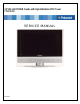
26” HD-LCD TV/DVD Combo with High Definition ATSC Tuner FXM-2611C SERVICE MANUAL 20061220
Important Service and Safety Information Prior to using this service manual, please ensure that you have carefully followed all the procedures outlined in the user's manual for this product. (1) Read all of these instructions. (2) Save these instructions. (3) Follow all warnings and instructions marked on the product. (4) Unplug this product from the wall outlet before cleaning. Do not use liquid cleaners or aerosol cleaners; use a damp cloth for cleaning. (5) Do not use this product near water.
Important Service and Safety Information Service work should be performed only by qualified service technicians familiar with all safety checks and these service guidelines: ELECTRIC SHOCK HAZARD Always disconnect AC power before servicing! Never modify any circuit! Never insert any objects into the holes in the TV case! ELECTROSTATIC DISCHARGE (ESD) Components inside an LCD or plasma TV are sensitive to static electricity.
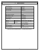
Table of Contents 1. 2. 3. 4. 5. 6. Specifications ...................................................................................................................................... 5 Operation............................................................................................................................................ 7 Troubleshooting Flow Chart................................................................................................................
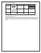
1. Specifications FXM-2611C Specifications: TFT-LCD Resolution 1366x768 TFT-LCD Screen Size 26 inches Laser Wavelength 780/650 nm Video System NTSC Frequency Response 20Hz-20kHz Audio Signal-to-noise Ratio ≥85dB Audio distortion + noise ≤70dB (1kHz) Channel Separation ≥70dB (1kHz) Dynamic Range ≥80dB (1kHz) ±2.5dB 0.2 Audio Out Analog Audio Out Out Level: 1.5V±1.0 , Load: 10KΩ Video Out Video Out Out Level: 1VP-P±0.
Discs Formats Supported By This Player: DISC LOGO • • CONTENTS SIZE DVD Audio + Video (movies) 12cm CD Audio 12cm JPEG Still Photographs 12cm MAXIMUM TIME 133min(SS-SL) 242min(SS-DL) 266min(DS-SL) 484min(DS-DL) 74min The operating method of some DVD discs is specified by the software maker. Please refer to the instruction manual of the disc.
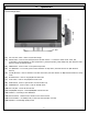
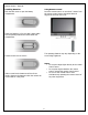
2. Operation Front and Right View: (1) 26" Color TFT screen - Offers a crystal clear image. (2) INPUT button - Press to enter the Input menu and then use the buttons to select mode: Tuner, AV1 (Composite 1), AV2 (Composite 2), AV3 (Component 1), AV4 (Component), VGA, HDMI, DVD, then press the Enter button to enter the selected mode. (3) MENU button - Press to enter or exit system setup menu. (4) CH ▲/▼button - In TV mode, press to select channels.
Rear View: (1) Y/Pr(Cr)/Pb(Cb) and L/R audio Input Jacks - Connectors for the Y/Pr(Cr)/Pb(Cb) input in AV3 (Component) mode. (2) Y/Pr(Cr)/Pb(Cb) and L/R audio Input Jacks - Connectors for the Y/Pr(Cr)/Pb(Cb) input in AV4 (Component) mode. (3) Video and L/R audio Input Jacks - Connectors for the audio and video signal input in AV1 (Composite) mode. (4) Video/S-VIDEO and L/R audio Input Jacks - Connectors for the audio and video/S-Video signal input in AV2 (Composite) mode.
Remote Control – General: Using Remote control Point the remote control no more than 7 meters from the remote control sensor and within about 60 degrees of the front of the unit. Installing Batteries Push the back cover to open the battery compartment. Insert two batteries (1.5V, size AAA), please make sure the polarity matches the marks inside the compartment. Press the back cover to close it. The operating distance may vary depending on the surrounding brightness.
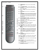
Remote Control – TV Mode: (1) POWER button - Press to enter or exit the standby mode. (2) 0~9 Number buttons - Press to select numbers. (3) MTS button - In TV mode, press to shift among SAP, Mono or Stereo mode. (4) VOL +/- button - Press to increase or decrease the volume. (5) MUTE button - Press to turn on or off the speaker output.
Remote Control – DVD Mode: (1) Play button - Press to play the disc in DVD mode. (2) Pause button - In DVD mode, press to pause the playback or start step frame by frame playback. Press the PLAY button to resume normal playback. (3) Fast Reverse button - In DVD mode, press to search backward (4) Fast Forward button - In DVD mode, press to search forward. (5) 0~9 Number buttons - Press to select numbers.
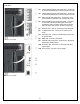
Moving the DVD Disc Tray: CAUTION: Before removing or installing the DVD disc tray, unplug the power supply cord. This unit is designed with a movable DVD Disc Tray. The Disc Tray can be installed in three different positions giving you the ability to maximize space and convenience. Follow the procedure (below) to remove and reinstall. Remove the DVD Disc Tray: Step 1: Open the back cover by sliding the left rear panel of the unit outward. Step 2: Remove the DVD disc tray.
3. Troubleshooting Flow Chart START Power on Does LED change color? N 1. Check connection between Power Board and Main Board 2. Check Power Board output voltage Y Does Backlight power on? N 1. Check connection between Power Board and LCD Module 2. Check Main Board J32 Backlight Control Y Does OSD appear? N 1. Check LVDS connector Y N Does Remote Control work? 1. Check connection between Remote Board and Main Board 2. Check ATMAGE8 pin 23 3.
A Do channels save correctly? N 1. Check CAS-220 2. Check connect circuit between tuner and CAS-220 3. Check control circuit between main chip (ZR39660) and CAS-220 N 1. Check video and audio switch chip (FASV330/331, CD4052) and relevant circuit 2. Check control circuit between main chip and switch chip Y Can you change sources? Y Can you change SRS mode? N Y Does the display look correct? N NOTE: Some Inputs don’t support SRS mode 1. Check AP8206AA chip 2.
4. Polaroid Display Cell Defect Specification In some cases, a panel may have defective cells that cannot be controlled.
5. Before Returning This Product to the User Before returning this product to the user, always perform the following safety checks: (1) Inspect all wiring to be sure no wires are pinched between the chassis or any metal parts. (2) Inspect all protective devices for proper installation, including non-metallic controls, insulation materials, cabinet backs, compartment covers, and shields.
6. Disassembly Procedure Note: Before disassembly of any part the TV, make sure the power is OFF, and the power cord is removed from the wall outlet. Allow time for power within all system boards to discharge before you begin disassembly. Never insert any objects into the vent holes in the TV case. Note: Before returning this product to the end user, you must follow the steps outlined in the section, Before Returning This Product to the User, on page 16.
Rear Cover Removal (1) Lay TV flat on workbench. Be careful to protect the front bezel and LCD screen from being scratched. Use protective cloth between work bench and TV front. (2) Remove back covers A, B, and C. A C B (3) Remove DVD Player (A), Cable (B), and Stand Cover (C).
(4) Remove six (6) screws from the TV Stand (A) and remove the stand from the TV. A (5) A Remove all screws from the rear cover (Location A). A A A (6) Remove all screws from the rear panel label area (A) and remove rear cover.
Main Board Removal and Replacement (1) DVD Module Board (2) Power Board (3) Main Board (4) Control Button Board (5) Speakers Note: Before disassembly of any part the TV, make sure the power is OFF, and the power cord is removed from the wall outlet. Allow time for power within all system boards to discharge before you begin disassembly. Never insert any objects into the vent holes in the TV case. (1) Remove rear cover and baffles as shown in the section, Disassembly Procedure on page 17.
(3) Disconnect cables on Main Board. (4) Remove all screws from the Main Board (Location A and B) and remove. A A B Note: Before returning this product to the end user, you must follow the steps outlined in the section, Before Returning This Product to the User, on page 16. This procedure ensures that the chassis will not cause electric shock.
Control Button Board Removal and Replacement (1) DVD Module Board (2) Power Board (3) Main Board (4) Control Button Board (5) Speakers Note: Before disassembly of any part the TV, make sure the power is OFF, and the power cord is removed from the wall outlet. Allow time for power within all system boards to discharge before you begin disassembly. Never insert any objects into the vent holes in the TV case.
DVD Module Board Removal and Replacement (1) DVD Module Board (2) Power Board (3) Main Board (4) Control Button Board (5) Speakers Note: Before disassembly of any part the TV, make sure the power is OFF, and the power cord is removed from the wall outlet. Allow time for power within all system boards to discharge before you begin disassembly. Never insert any objects into the vent holes in the TV case. A (1) Remove rear cover and baffles as shown in the section, Disassembly Procedure on page 17.
Power Board Removal and Replacement (1) DVD Module Board (2) Power Board (3) Main Board (4) Control Button Board (5) Speakers Note: Before disassembly of any part the TV, make sure the power is OFF, and the power cord is removed from the wall outlet. Allow time for power within all system boards to discharge before you begin disassembly. Never insert any objects into the vent holes in the TV case. (1) Remove rear cover and baffles as shown in the section, Disassembly Procedure on page 17.
IR / Power LED Board Removal and Replacement (1) DVD Module Board (2) Power Board (3) Main Board (4) Control Button Board (5) Speakers Note: Before disassembly of any part the TV, make sure the power is OFF, and the power cord is removed from the wall outlet. Allow time for power within all system boards to discharge before you begin disassembly. Never insert any objects into the vent holes in the TV case.
7.
8.
9.
Video Signal Processing Block Diagram Power on N Input signal set to Tuner or Composite? Input signal set to HDMI? Y Y Process Circuit ATSC digital signal Process Circuit Y N Input signal set to Component or VGA Y Process Circuit Switch Chip FSAV330/331 X6941 IF Filter N Oren Switch Chip FSAV330/331 CAS-220 MST9883 ADC FMS6408 DDR333 RAM 512M (256M*2) ZR39660 (Main Chip) LVDS 29 SDRAM 32M
10.
Audio I/O 31
Video I/O 32
HDMI I/O 33
1394 34
Module Board 35
Front Panel Connectors Backlight 36
IR Board Reset Circuit 37
11.
Main Board (Bottom view) 39
Control Button board top view Control Button board bottom view Remote board top view Remote board bottom view DVD Module board top view DVD Module board bottom view 40